How to Use Digital Brushless DC Motor Driver 12V-48VDC Max 15.0A 400W: Examples, Pinouts, and Specs

Introduction
The Digital Brushless DC Motor Driver (Model: BLD-510B), manufactured by Stepper Online, is a high-performance motor driver designed to control brushless DC (BLDC) motors. It operates within a voltage range of 12V to 48V DC, supports a maximum current of 15A, and delivers up to 400W of power. This driver is ideal for applications requiring precise motor control, high efficiency, and reliability.
Explore Projects Built with Digital Brushless DC Motor Driver 12V-48VDC Max 15.0A 400W

Explore Projects Built with Digital Brushless DC Motor Driver 12V-48VDC Max 15.0A 400W
Common Applications and Use Cases
- Industrial automation systems
- Robotics and robotic arms
- CNC machines
- Electric vehicles and e-bikes
- Conveyor belts and material handling systems
- Fans, pumps, and other motor-driven devices
Technical Specifications
Key Technical Details
| Parameter | Specification |
|---|---|
| Input Voltage Range | 12V - 48V DC |
| Maximum Current | 15.0A |
| Maximum Power Output | 400W |
| Motor Type Supported | Brushless DC (BLDC) |
| Control Signal Input | PWM, Analog Voltage, or Direction |
| Speed Control Range | 0% - 100% |
| Operating Temperature | -10°C to +50°C |
| Dimensions | 118mm x 85mm x 35mm |
| Weight | 300g |
Pin Configuration and Descriptions
The BLD-510B motor driver features a set of input/output terminals for power, motor connections, and control signals. Below is the pin configuration:
Power and Motor Connections
| Pin Name | Description |
|---|---|
| V+ | Positive DC power input (12V-48V) |
| V- | Negative DC power input (GND) |
| U | Motor phase U connection |
| V | Motor phase V connection |
| W | Motor phase W connection |
Control Signal Inputs
| Pin Name | Description |
|---|---|
| ENA | Enable signal input (active high) |
| PWM | PWM signal input for speed control |
| DIR | Direction control input (high/low) |
| VR | Analog voltage input for speed control (0-5V) |
| GND | Ground for control signals |
Usage Instructions
How to Use the Component in a Circuit
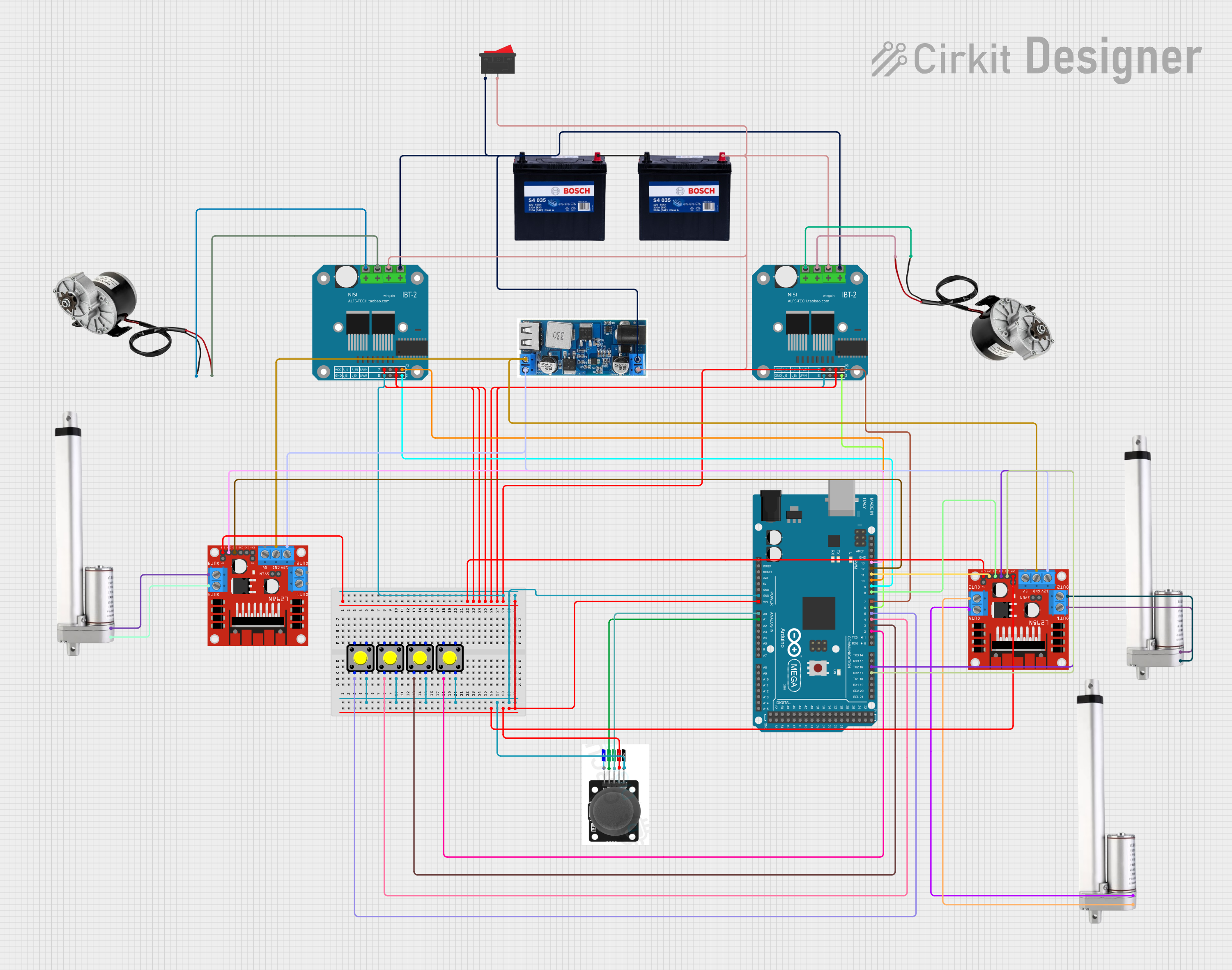
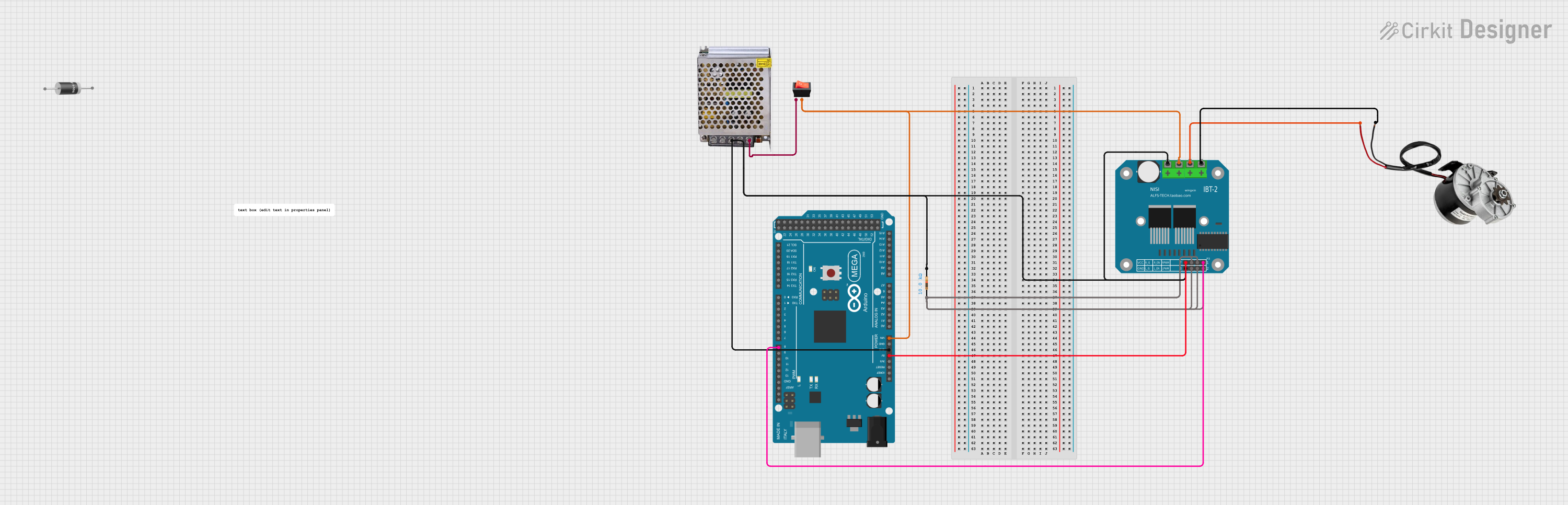
- Power Supply: Connect a DC power supply (12V-48V) to the
V+andV-terminals. Ensure the power supply can provide sufficient current for the motor and driver (e.g., 15A for maximum load). - Motor Connection: Connect the three motor phases (
U,V,W) to the corresponding terminals on the driver. Ensure the motor is a compatible brushless DC motor. - Control Signals:
- For PWM speed control, connect a PWM signal (e.g., from a microcontroller) to the
PWMpin. - For direction control, connect a digital signal to the
DIRpin (high for one direction, low for the opposite). - Alternatively, use the
VRpin for analog voltage speed control (0-5V).
- For PWM speed control, connect a PWM signal (e.g., from a microcontroller) to the
- Enable Signal: Connect the
ENApin to a high signal to enable the driver. Leave it low to disable the driver. - Grounding: Ensure all ground connections (
V-andGND) are properly connected to avoid signal noise or instability.
Important Considerations and Best Practices
- Heat Dissipation: The driver may generate heat during operation. Use a heatsink or active cooling if operating near the maximum current or power limits.
- Wiring: Use appropriately rated wires for power and motor connections to handle the current without overheating.
- Signal Isolation: If using a microcontroller, ensure proper isolation (e.g., optocouplers) to protect the controller from voltage spikes.
- Startup Testing: Start with a low-speed setting to verify the motor and driver connections before full operation.
Example: Using with Arduino UNO
Below is an example of controlling the BLD-510B with an Arduino UNO using PWM for speed control and a digital pin for direction control.
// Define pin connections
const int pwmPin = 9;  // PWM signal output
const int dirPin = 8;  // Direction control
const int enaPin = 7;  // Enable signal

void setup() {
  // Set pin modes
  pinMode(pwmPin, OUTPUT);
  pinMode(dirPin, OUTPUT);
  pinMode(enaPin, OUTPUT);

  // Enable the motor driver
  digitalWrite(enaPin, HIGH);  // Set ENA high to enable the driver
}

void loop() {
  // Set motor direction
  digitalWrite(dirPin, HIGH);  // HIGH for one direction, LOW for the other

  // Set motor speed using PWM
  analogWrite(pwmPin, 128);  // 50% duty cycle (range: 0-255)

  delay(5000);  // Run for 5 seconds

  // Change direction
  digitalWrite(dirPin, LOW);  // Reverse direction
  delay(5000);  // Run for 5 seconds
}
Troubleshooting and FAQs
Common Issues and Solutions
Motor Does Not Spin:
- Check the power supply voltage and current rating.
- Verify motor connections (
U,V,W) are correct. - Ensure the
ENApin is set high to enable the driver.
Motor Spins in the Wrong Direction:
- Reverse the signal on the
DIRpin or swap two motor phase wires.
- Reverse the signal on the
Driver Overheats:
- Ensure proper ventilation or add a heatsink.
- Reduce the motor load or operating current.
PWM Control Not Working:
- Verify the PWM signal frequency (recommended: 1kHz to 20kHz).
- Check the connection between the microcontroller and the
PWMpin.
Analog Voltage Control Not Working:
- Ensure the voltage on the
VRpin is within the 0-5V range. - Check for proper grounding between the driver and the control source.
- Ensure the voltage on the
FAQs
Q: Can I use this driver with a 24V power supply?
A: Yes, the driver supports a voltage range of 12V to 48V, so 24V is within the acceptable range.
Q: What type of motors are compatible with this driver?
A: The BLD-510B is designed for 3-phase brushless DC motors.
Q: Is it possible to control the speed without a microcontroller?
A: Yes, you can use the VR pin with a potentiometer to control the speed via analog voltage.
Q: What is the recommended PWM frequency?
A: The recommended PWM frequency is between 1kHz and 20kHz for optimal performance.
Q: Does the driver have built-in protection features?
A: Yes, the driver includes overcurrent, overvoltage, and thermal protection to ensure safe operation.