How to Use Voltage Sensor: Examples, Pinouts, and Specs
Introduction
A voltage sensor is a device designed to measure the electrical potential difference between two points in a circuit. It provides real-time voltage readings, which are essential for monitoring and analyzing electrical systems. Voltage sensors are widely used in applications such as battery monitoring, power supply regulation, renewable energy systems, and embedded electronics projects.
Common use cases include:
- Monitoring battery voltage in portable devices or electric vehicles.
- Measuring voltage levels in solar panels or wind turbines.
- Ensuring safe operation of power supplies in industrial systems.
- Integrating with microcontrollers (e.g., Arduino) for data acquisition and control.
Explore Projects Built with Voltage Sensor

Explore Projects Built with Voltage Sensor
Technical Specifications
Below are the general technical specifications for a typical voltage sensor module (e.g., a voltage divider-based sensor like the commonly used "Voltage Sensor Module for Arduino"):
| Parameter | Value |
|---|---|
| Input Voltage Range | 0V to 25V (typical) |
| Output Voltage Range | 0V to 5V (scaled for microcontroller ADC) |
| Voltage Divider Ratio | 5:1 (input voltage scaled down by 5) |
| Accuracy | ±1% (typical, depending on resistor tolerances) |
| Operating Voltage | 3.3V or 5V (compatible with most microcontrollers) |
| Dimensions | ~30mm x 15mm x 10mm |
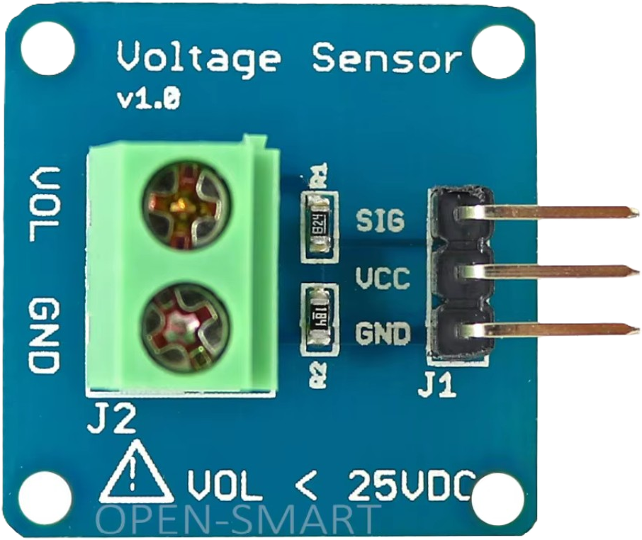
Pin Configuration
The voltage sensor module typically has the following pinout:
| Pin Name | Description |
|---|---|
VCC |
Power supply input (3.3V or 5V, depending on the module) |
GND |
Ground connection |
VIN+ |
Positive input for the voltage to be measured |
VIN- |
Negative input for the voltage to be measured (often tied to GND) |
VOUT |
Scaled output voltage (connect to microcontroller ADC) |
Usage Instructions
How to Use the Voltage Sensor in a Circuit
- Power the Module: Connect the
VCCpin to a 3.3V or 5V power source, and connect theGNDpin to the ground of your circuit. - Connect the Voltage to be Measured:
- Attach the positive terminal of the voltage source to the
VIN+pin. - Attach the negative terminal of the voltage source to the
VIN-pin (or GND if the module uses a common ground).
- Attach the positive terminal of the voltage source to the
- Read the Scaled Output:
- The
VOUTpin provides a scaled-down voltage proportional to the input voltage. Connect this pin to an analog input pin of a microcontroller (e.g., Arduino). - Use the microcontroller's ADC to read the voltage and calculate the actual input voltage using the voltage divider ratio.
- The
Important Considerations and Best Practices
- Voltage Range: Ensure the input voltage does not exceed the module's maximum rating (e.g., 25V). Exceeding this limit can damage the sensor.
- Accuracy: The accuracy of the sensor depends on the resistor tolerances in the voltage divider. For critical applications, consider calibrating the sensor.
- Common Ground: If the voltage source and the microcontroller do not share a common ground, the readings may be inaccurate or the module may not function correctly.
- Scaling Factor: For a 5:1 voltage divider, the actual input voltage can be calculated as:
[
V_{in} = V_{out} \times 5
]
where ( V_{out} ) is the voltage read from the
VOUTpin.
Example Code for Arduino UNO
Below is an example Arduino sketch to read and display the voltage using a voltage sensor:
// Define the analog pin connected to the voltage sensor's VOUT pin
const int sensorPin = A0;

// Define the voltage divider ratio (5:1 for this module)
const float voltageDividerRatio = 5.0;

// Define the reference voltage of the Arduino (5V for most boards)
const float referenceVoltage = 5.0;

void setup() {
  Serial.begin(9600); // Initialize serial communication at 9600 baud
}

void loop() {
  // Read the analog value from the sensor
  int sensorValue = analogRead(sensorPin);

  // Convert the analog value to a voltage (0-5V range)
  float outputVoltage = (sensorValue / 1023.0) * referenceVoltage;

  // Calculate the actual input voltage using the voltage divider ratio
  float inputVoltage = outputVoltage * voltageDividerRatio;

  // Print the input voltage to the Serial Monitor
  Serial.print("Input Voltage: ");
  Serial.print(inputVoltage);
  Serial.println(" V");

  delay(1000); // Wait for 1 second before taking the next reading
}
Troubleshooting and FAQs
Common Issues
Incorrect Voltage Readings:
- Cause: The voltage divider ratio is not accounted for in the calculations.
- Solution: Ensure you multiply the output voltage by the correct scaling factor (e.g., 5 for a 5:1 divider).
No Output or Fluctuating Readings:
- Cause: Poor connections or loose wires.
- Solution: Check all connections, especially the
VIN+andVIN-pins.
Microcontroller Reads 0V:
- Cause: The input voltage is below the sensor's measurable range or the
VOUTpin is not connected properly. - Solution: Verify the input voltage and ensure the
VOUTpin is connected to the correct analog input pin.
- Cause: The input voltage is below the sensor's measurable range or the
Sensor Overheating:
- Cause: Input voltage exceeds the module's maximum rating.
- Solution: Ensure the input voltage is within the specified range (e.g., 0-25V).
FAQs
Q: Can I use this sensor to measure AC voltage?
A: No, this sensor is designed for DC voltage only. Measuring AC voltage requires additional circuitry, such as a rectifier and filter.
Q: What happens if I connect a voltage higher than the maximum input?
A: Exceeding the maximum input voltage can damage the sensor and potentially the connected microcontroller. Always ensure the input voltage is within the specified range.
Q: Can I use this sensor with a 3.3V microcontroller?
A: Yes, the sensor is compatible with 3.3V systems, but ensure the output voltage does not exceed the ADC input range of your microcontroller.
Q: How do I improve the accuracy of the sensor?
A: Use precision resistors in the voltage divider or calibrate the sensor by comparing its readings with a known accurate multimeter.
By following this documentation, you can effectively integrate and use a voltage sensor in your projects for accurate voltage monitoring and analysis.