How to Use toilet emergency button: Examples, Pinouts, and Specs
Introduction
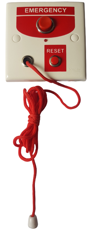
The Toilet Emergency Button is a safety device designed for installation in restrooms to provide a quick and reliable way for users to alert staff or emergency services during an emergency. It typically features a large, easily accessible button that can be activated with minimal effort, making it suitable for individuals with limited mobility or in distress. This device is commonly used in public restrooms, hospitals, elderly care facilities, and accessible bathrooms to enhance safety and ensure prompt assistance.
Explore Projects Built with toilet emergency button

Explore Projects Built with toilet emergency button
Common Applications and Use Cases
- Public restrooms in malls, airports, and train stations
- Accessible bathrooms for individuals with disabilities
- Hospitals and healthcare facilities
- Elderly care homes and assisted living facilities
- High-risk areas where immediate assistance may be required
Technical Specifications
Key Technical Details
- Operating Voltage: 12V DC (typical)
- Current Consumption: ≤ 50mA
- Output Type: Normally Open (NO) or Normally Closed (NC) relay contacts
- Button Type: Large, momentary push-button with tactile feedback
- Indicator: Integrated LED or buzzer for activation confirmation (optional)
- Material: Durable ABS plastic or stainless steel housing
- Mounting: Wall-mounted with screws or adhesive backing
- Environmental Rating: IP65 (water-resistant)
Pin Configuration and Descriptions
The Toilet Emergency Button typically has a terminal block with the following connections:
| Pin | Label | Description |
|---|---|---|
| 1 | VCC | Connect to the positive terminal of the 12V DC power supply. |
| 2 | GND | Connect to the ground terminal of the power supply. |
| 3 | NO | Normally Open relay contact; closes when the button is pressed. |
| 4 | NC | Normally Closed relay contact; opens when the button is pressed. |
| 5 | COM | Common terminal for the relay contacts. |
Usage Instructions
How to Use the Component in a Circuit
Power Supply Connection:
Connect theVCCpin to a 12V DC power source and theGNDpin to the ground. Ensure the power supply is stable and within the specified voltage range.Relay Output Wiring:
- For a Normally Open (NO) configuration, connect the load (e.g., alarm, light, or buzzer) between the
NOandCOMpins. The circuit will close when the button is pressed. - For a Normally Closed (NC) configuration, connect the load between the
NCandCOMpins. The circuit will open when the button is pressed.
- For a Normally Open (NO) configuration, connect the load (e.g., alarm, light, or buzzer) between the
Mounting the Button:
Secure the button to the wall using screws or adhesive backing. Ensure it is installed at an accessible height, typically 85-100 cm from the floor.Testing the System:
After installation, press the button to verify that the connected alarm or indicator activates as expected. Check both the NO and NC configurations if applicable.
Important Considerations and Best Practices
- Accessibility: Install the button at a height and location that is easily reachable for all users, including those in wheelchairs.
- Visibility: Ensure the button is clearly marked and visible, often with a red color or emergency symbol.
- Maintenance: Regularly test the button and connected systems to ensure proper functionality. Replace worn-out components as needed.
- Integration: For advanced systems, the button can be connected to a central monitoring system or IoT platform for remote alerts.
Arduino UNO Example Code
If you wish to integrate the Toilet Emergency Button with an Arduino UNO for testing or IoT applications, you can use the following code:
// Arduino code to monitor a Toilet Emergency Button and activate a buzzer
// when the button is pressed. The button is connected to pin 2, and the
// buzzer is connected to pin 8.

const int buttonPin = 2;  // Pin connected to the button's NO terminal
const int buzzerPin = 8;  // Pin connected to the buzzer

void setup() {
  pinMode(buttonPin, INPUT_PULLUP);  // Set button pin as input with pull-up resistor
  pinMode(buzzerPin, OUTPUT);       // Set buzzer pin as output
  digitalWrite(buzzerPin, LOW);     // Ensure buzzer is off initially
}

void loop() {
  int buttonState = digitalRead(buttonPin);  // Read the button state

  if (buttonState == LOW) {  // Button pressed (active LOW)
    digitalWrite(buzzerPin, HIGH);  // Turn on the buzzer
  } else {
    digitalWrite(buzzerPin, LOW);   // Turn off the buzzer
  }
}
Note: The button's NO terminal should be connected to pin 2, and the COM terminal should be connected to the Arduino's ground. The buzzer's positive terminal should be connected to pin 8, and its negative terminal to ground.
Troubleshooting and FAQs
Common Issues and Solutions
Button Does Not Trigger the Alarm:
- Verify the power supply connections to the
VCCandGNDpins. - Check the wiring between the relay output and the connected load.
- Ensure the button is not physically damaged or obstructed.
- Verify the power supply connections to the
False Alarms or Continuous Activation:
- Inspect the wiring for short circuits or loose connections.
- Ensure the button is not stuck in the pressed position.
No Response from Arduino:
- Confirm that the button is connected to the correct Arduino pin.
- Check the Arduino code for errors and ensure the correct pin numbers are used.
- Use a multimeter to verify the button's NO and COM terminals are functioning properly.
FAQs
Can the button be used outdoors?
Yes, if the button has an IP65 or higher rating, it can be used in outdoor environments.What type of alarm can be connected?
Any device compatible with the relay's voltage and current ratings, such as buzzers, lights, or sirens.Can the button be integrated with a wireless system?
Yes, the relay output can be connected to a wireless transmitter or IoT module for remote alerts.How often should the button be tested?
It is recommended to test the button and connected systems at least once a month to ensure reliability.