How to Use pc817 optotransistor: Examples, Pinouts, and Specs
Introduction
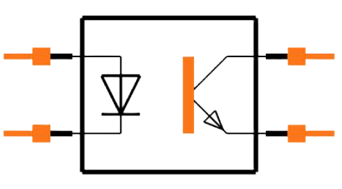
The PC817 is a widely used optocoupler or optoisolator that consists of an infrared emitting diode (IRED) and a phototransistor. This electronic component is designed to transfer electrical signals through light waves, providing an optical isolation between its input and output. The PC817 is commonly used in applications requiring high-voltage insulation, signal isolation, and noise reduction, such as microcontroller interfacing, DC-DC converters, and signal transmission between different voltage circuits without direct electrical connection.
Explore Projects Built with pc817 optotransistor
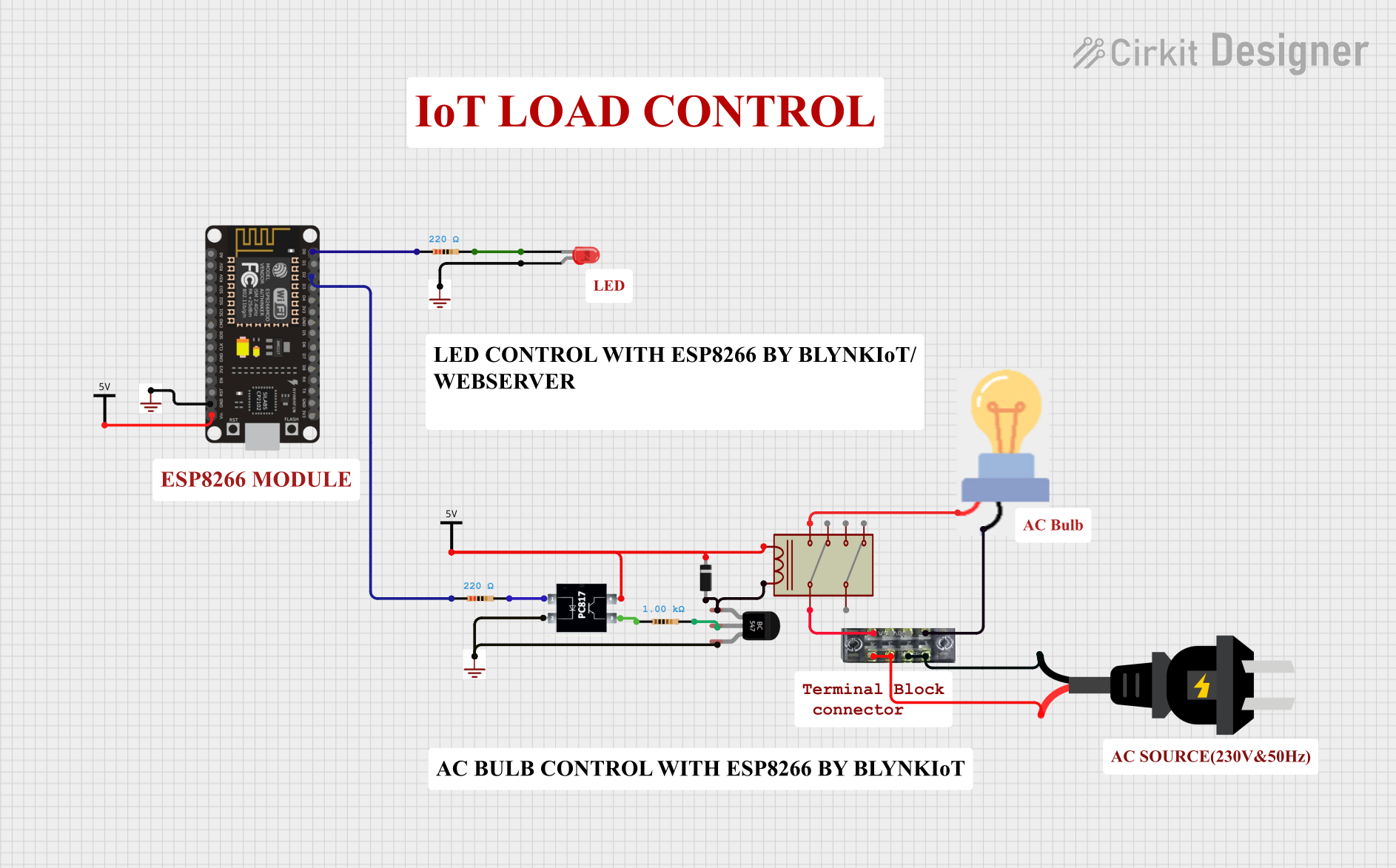
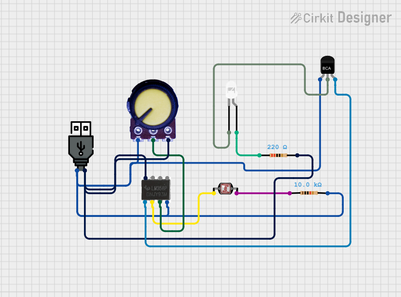
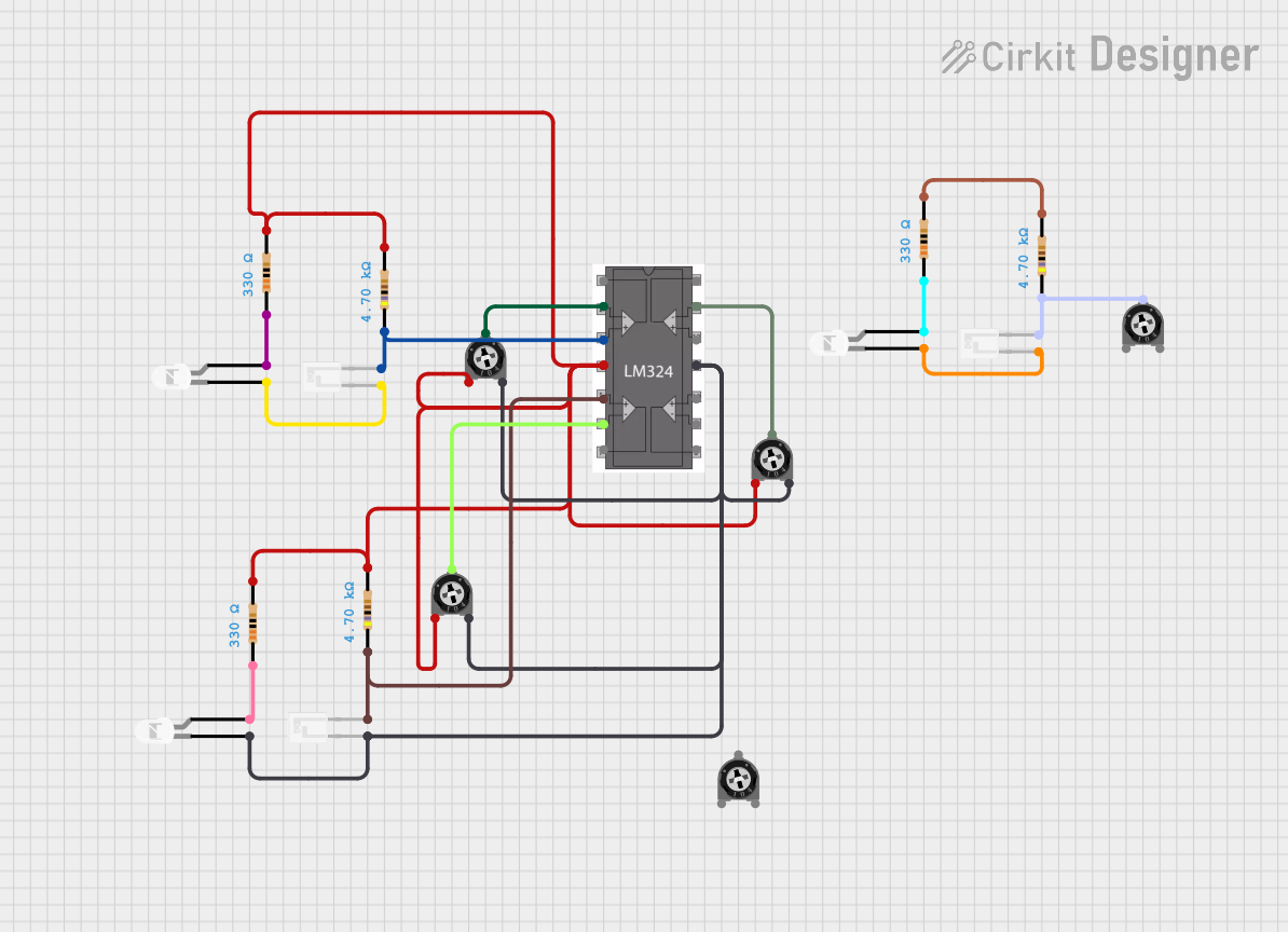
Explore Projects Built with pc817 optotransistor
Technical Specifications
Key Technical Details
- Forward Current (IF): 50mA (max)
- Reverse Voltage (VR): 6V (max)
- Collector-Emitter Voltage (VCEO): 35V (max)
- Emitter-Collector Voltage (VECO): 6V (max)
- Collector Current (IC): 50mA (max)
- Isolation Voltage (Viso): 5000Vrms (min)
- Current Transfer Ratio (CTR): 50% to 600% at IF=5mA, VCE=5V
- Response Time (tr): 18µs (typ), 100µs (max)
- Operating Temperature: -30°C to +100°C
Pin Configuration and Descriptions
| Pin Number | Name | Description |
|---|---|---|
| 1 | Anode (A) | Anode of the infrared emitting diode |
| 2 | Cathode (K) | Cathode of the infrared emitting diode |
| 3 | Collector (C) | Collector of the phototransistor |
| 4 | Emitter (E) | Emitter of the phototransistor |
Usage Instructions
How to Use the PC817 in a Circuit
Connecting the Input Side (LED):
- Connect the anode to the positive side of the input signal.
- Connect the cathode to the negative side of the input signal through a current-limiting resistor.
Connecting the Output Side (Phototransistor):
- Connect the collector to the positive side of the output circuit.
- Connect the emitter to the negative side of the output circuit.
Current Limiting Resistor Calculation:
- Calculate the current-limiting resistor for the LED side using Ohm's law:
R = (Vin - Vf) / If, whereVinis the input voltage,Vfis the forward voltage of the LED (typically 1.2V), andIfis the desired forward current (typically 10-20mA).
- Calculate the current-limiting resistor for the LED side using Ohm's law:
Important Considerations and Best Practices
- Ensure that the input and output circuits are properly isolated to prevent electrical noise and high-voltage transients from affecting the low-voltage side.
- Do not exceed the maximum ratings of the device to avoid damage.
- Use a pull-up resistor on the collector of the phototransistor for proper operation.
- Consider the current transfer ratio (CTR) when designing your circuit to ensure adequate signal transfer.
Troubleshooting and FAQs
Common Issues
- No Signal Transfer: Check if the input LED is properly forward-biased and the current-limiting resistor is correctly calculated.
- Weak Output Signal: Ensure that the CTR is within the required range for your application and that the phototransistor is not saturated.
- Device Damage: Verify that the device is not exposed to voltages or currents beyond its maximum ratings.
Solutions and Tips
- If the LED does not light up, check the input connections and the current-limiting resistor.
- For a weak output signal, adjust the value of the pull-up resistor or check the input current to the LED.
- Use a multimeter to check the continuity of the PC817 pins to ensure the device is not damaged.
FAQs
Q: Can the PC817 be used to isolate high-voltage circuits? A: Yes, the PC817 provides electrical isolation up to 5000Vrms, making it suitable for high-voltage applications.
Q: What is the purpose of the current-limiting resistor on the input side? A: The current-limiting resistor protects the LED from excessive current, which could lead to damage or reduced lifespan.
Q: How do I choose the pull-up resistor value for the phototransistor? A: The pull-up resistor value depends on the voltage level of the output circuit and the desired collector current. It can be calculated using Ohm's law, considering the CTR and the collector-emitter voltage.
Example Code for Arduino UNO
// Example code for interfacing PC817 with Arduino UNO

const int inputPin = 2; // Input pin connected to the phototransistor
const int ledPin = 13;  // Onboard LED pin for output indication

void setup() {
  pinMode(inputPin, INPUT); // Set the phototransistor pin as input
  pinMode(ledPin, OUTPUT);  // Set the LED pin as output
}

void loop() {
  int sensorValue = digitalRead(inputPin); // Read the value from the optotransistor
  if (sensorValue == HIGH) {
    digitalWrite(ledPin, HIGH); // Turn on the LED if the sensor is triggered
  } else {
    digitalWrite(ledPin, LOW);  // Turn off the LED otherwise
  }
}
Remember to include a current-limiting resistor for the LED side of the PC817 when connecting it to the Arduino. The example assumes that the PC817 output is connected to pin 2 and that the onboard LED is used as an output indicator. Adjust the pin numbers as necessary for your specific circuit design.