Cirkit Designer Logo
Cirkit Designer
Your all-in-one circuit design IDE
Home / 
Component Documentation

How to Use 1N4148 diode: Examples, Pinouts, and Specs

Image of 1N4148 diode
Cirkit Designer LogoDesign with 1N4148 diode in Cirkit Designer

Introduction

The 1N4148 is a widely used general-purpose, small-signal diode known for its high-speed switching capabilities. It is commonly employed in electronic circuits for various applications such as signal rectification, signal demodulation, voltage clamping, and protection against voltage spikes. Due to its versatility, it is a staple in both hobbyist and professional electronic projects.

Explore Projects Built with 1N4148 diode

Use Cirkit Designer to design, explore, and prototype these projects online. Some projects support real-time simulation. Click "Open Project" to start designing instantly!
Piezo Sensor-Based LED Indicator with Pushbutton Control
Image of project: A project utilizing 1N4148 diode in a practical application
This circuit is a rectifier and indicator system that uses multiple 1N4007 diodes to rectify an AC signal, a piezo sensor for signal detection, and a pushbutton to control the circuit. The rectified signal is filtered by an electrolytic capacitor and a resistor, and the presence of the signal is indicated by a blue LED.
Cirkit Designer LogoOpen Project in Cirkit Designer
Rectifier Diode and LED Circuit with Rocker Switch Control
Image of hypihygi innovations: A project utilizing 1N4148 diode in a practical application
This circuit appears to be a simple power supply circuit with a protection diode and an LED indicator. The diode ensures current flows in only one direction, protecting the circuit from reverse polarity damage. A rocker switch is used to control the power to the LED, which likely serves as an indicator for when the power is on.
Cirkit Designer LogoOpen Project in Cirkit Designer
12V to 5V Power Supply with LED Indicator and Push Switch
Image of Power Supply LVCO: A project utilizing 1N4148 diode in a practical application
This circuit is a 12V to 5V regulated power supply with an LED indicator. It uses a 5408 diode for reverse polarity protection, an LM340T5 7805 voltage regulator to step down the voltage to 5V, and a push switch to control the LED indicator. The circuit also includes capacitors for filtering and a resistor to limit the current through the LED.
Cirkit Designer LogoOpen Project in Cirkit Designer
Diode and Capacitor-Based Voltage Regulation Circuit
Image of Pavetra#2: A project utilizing 1N4148 diode in a practical application
This circuit is a complex network of diodes and electrolytic capacitors connected to two terminal PCB 2-pin connectors. The diodes are arranged in a series-parallel configuration, while the capacitors are connected in a manner that suggests filtering or energy storage purposes. The overall design appears to be aimed at rectification and smoothing of an input signal.
Cirkit Designer LogoOpen Project in Cirkit Designer

Explore Projects Built with 1N4148 diode

Use Cirkit Designer to design, explore, and prototype these projects online. Some projects support real-time simulation. Click "Open Project" to start designing instantly!
Image of project: A project utilizing 1N4148 diode in a practical application
Piezo Sensor-Based LED Indicator with Pushbutton Control
This circuit is a rectifier and indicator system that uses multiple 1N4007 diodes to rectify an AC signal, a piezo sensor for signal detection, and a pushbutton to control the circuit. The rectified signal is filtered by an electrolytic capacitor and a resistor, and the presence of the signal is indicated by a blue LED.
Cirkit Designer LogoOpen Project in Cirkit Designer
Image of hypihygi innovations: A project utilizing 1N4148 diode in a practical application
Rectifier Diode and LED Circuit with Rocker Switch Control
This circuit appears to be a simple power supply circuit with a protection diode and an LED indicator. The diode ensures current flows in only one direction, protecting the circuit from reverse polarity damage. A rocker switch is used to control the power to the LED, which likely serves as an indicator for when the power is on.
Cirkit Designer LogoOpen Project in Cirkit Designer
Image of Power Supply LVCO: A project utilizing 1N4148 diode in a practical application
12V to 5V Power Supply with LED Indicator and Push Switch
This circuit is a 12V to 5V regulated power supply with an LED indicator. It uses a 5408 diode for reverse polarity protection, an LM340T5 7805 voltage regulator to step down the voltage to 5V, and a push switch to control the LED indicator. The circuit also includes capacitors for filtering and a resistor to limit the current through the LED.
Cirkit Designer LogoOpen Project in Cirkit Designer
Image of Pavetra#2: A project utilizing 1N4148 diode in a practical application
Diode and Capacitor-Based Voltage Regulation Circuit
This circuit is a complex network of diodes and electrolytic capacitors connected to two terminal PCB 2-pin connectors. The diodes are arranged in a series-parallel configuration, while the capacitors are connected in a manner that suggests filtering or energy storage purposes. The overall design appears to be aimed at rectification and smoothing of an input signal.
Cirkit Designer LogoOpen Project in Cirkit Designer

Technical Specifications

Key Technical Details

  • Material: Silicon
  • Type: Small Signal Diode
  • Peak Repetitive Reverse Voltage (Vrrm): 100V
  • Continuous Forward Current (If): 200mA
  • Peak Forward Surge Current (Ifsm): 500mA (Pulse width ≤ 1s, Duty cycle ≤ 1%)
  • Forward Voltage Drop (Vf): 1.0V at If = 10mA
  • Reverse Current (Ir): 25nA at Vr = 20V
  • Junction Capacitance (Cj): 4pF at Vr = 0V, f = 1MHz
  • Reverse Recovery Time (trr): 4ns
  • Operating Junction Temperature Range: -65°C to +175°C

Pin Configuration and Descriptions

Pin Number Name Description
1 Anode The positive side of the diode, where current enters.
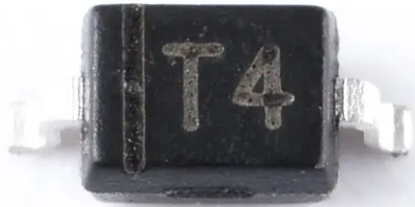
2 Cathode The negative side of the diode, marked by a band, where current exits.

Usage Instructions

How to Use the 1N4148 in a Circuit

  1. Directionality: Ensure the diode is oriented correctly in the circuit with the anode connected to the positive voltage and the cathode (marked by a band) connected to the negative side or ground.

  2. Current Limiting: Always use a current-limiting resistor to prevent the diode from exceeding its maximum forward current rating.

  3. Voltage Rating: Do not exceed the peak repetitive reverse voltage rating to avoid breakdown and potential damage to the diode.

  4. Signal Applications: For high-speed switching applications, place the diode where it can clamp or rectify small signals as needed.

Important Considerations and Best Practices

  • Temperature: Be mindful of the operating temperature range to prevent thermal runaway.
  • Mounting: Ensure proper mounting to avoid mechanical stress that could lead to cracking or breaking.
  • Soldering: Use appropriate soldering techniques to prevent damage due to excessive heat.

Troubleshooting and FAQs

Common Issues

  • Diode Not Conducting: Check for correct orientation and ensure that the forward voltage is being applied.
  • Unexpected Voltage Drops: Verify that the diode is not in a high-current situation that exceeds its maximum forward current rating.
  • Diode Damaged by Reverse Voltage: Ensure that the reverse voltage does not exceed the specified limit.

Solutions and Tips

  • Testing Diode Functionality: Use a multimeter in diode mode to check for forward and reverse bias functionality.
  • Heat Management: If the diode is running hot, consider using a heat sink or improving air circulation around the component.
  • Replacement: If the diode is damaged, it should be replaced as it cannot be repaired.

FAQs

Q: Can the 1N4148 be used for power rectification? A: No, the 1N4148 is designed for small-signal applications and is not suitable for power rectification.

Q: What is the maximum frequency the 1N4148 can handle for signal switching? A: The 1N4148 can handle high-frequency signals due to its fast reverse recovery time of 4ns, but the exact maximum frequency will depend on the specific circuit conditions.

Q: How can I identify the anode and cathode on the diode? A: The cathode is marked with a band on the diode's body, and the anode is the unmarked side.

Example Code for Arduino UNO

The 1N4148 diode can be used in conjunction with an Arduino UNO for various purposes, such as protecting inputs or outputs from reverse voltage spikes. Below is an example of how to use the 1N4148 to protect an Arduino input pin.

// Example code to demonstrate the use of a 1N4148 diode for input protection

void setup() {
  pinMode(2, INPUT); // Set digital pin 2 as an input
}

void loop() {
  int sensorValue = digitalRead(2); // Read the value from the protected input pin
  // Process the sensor value as needed
}

In this example, a 1N4148 diode would be connected in parallel with the input pin (anode to ground and cathode to the pin) to protect against negative voltage spikes. This is a simple use case and does not represent the full capabilities of the diode or the Arduino platform.