How to Use 2P Breaker: Examples, Pinouts, and Specs
Introduction
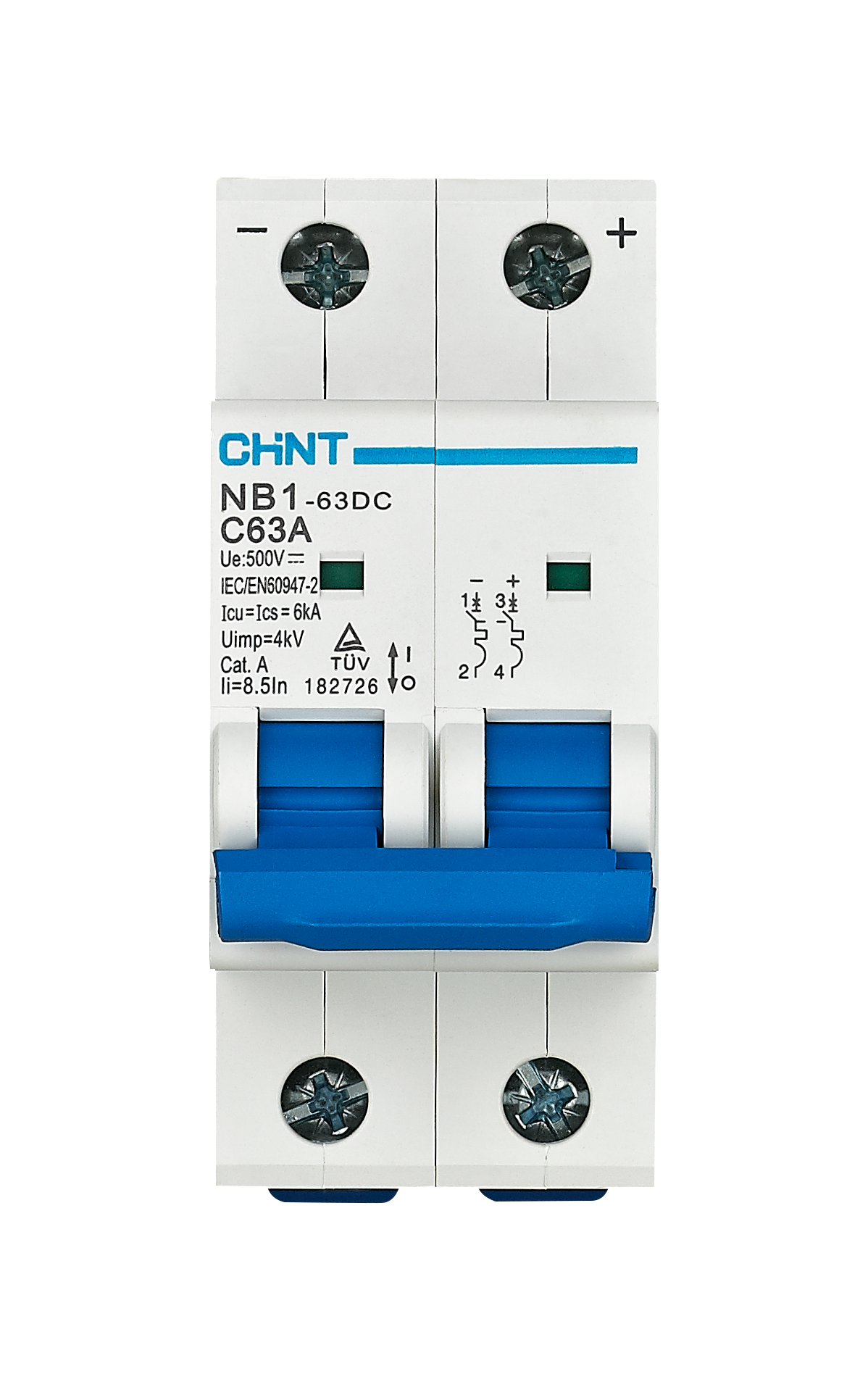
The 2P Breaker (Schneider MCB F1-2 Motor) is a 2-pole miniature circuit breaker designed to protect electrical circuits from overloads and short circuits. It ensures the safe interruption of current flow in dual-phase systems, making it an essential component for safeguarding electrical installations. Manufactured by Schneider, this breaker is known for its reliability, durability, and compliance with international safety standards.
Explore Projects Built with 2P Breaker
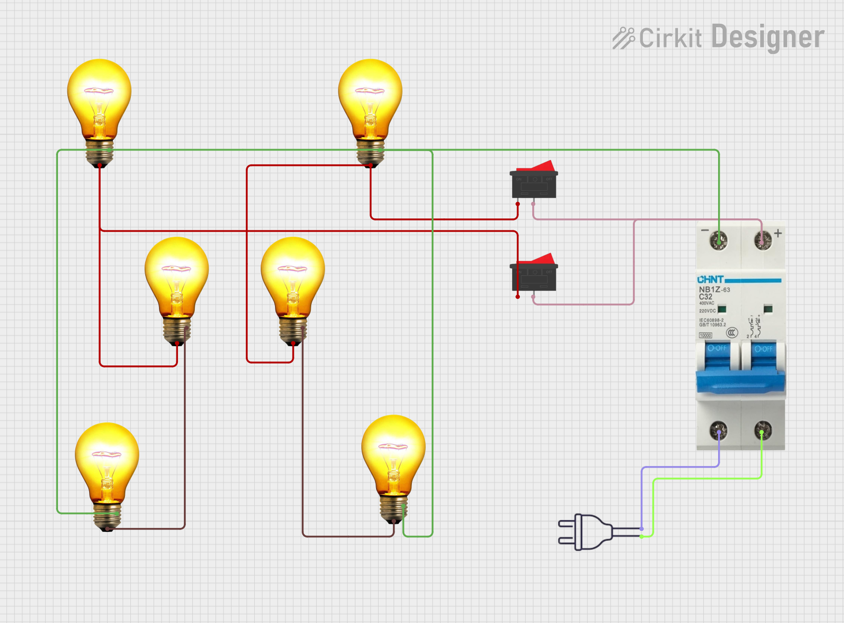

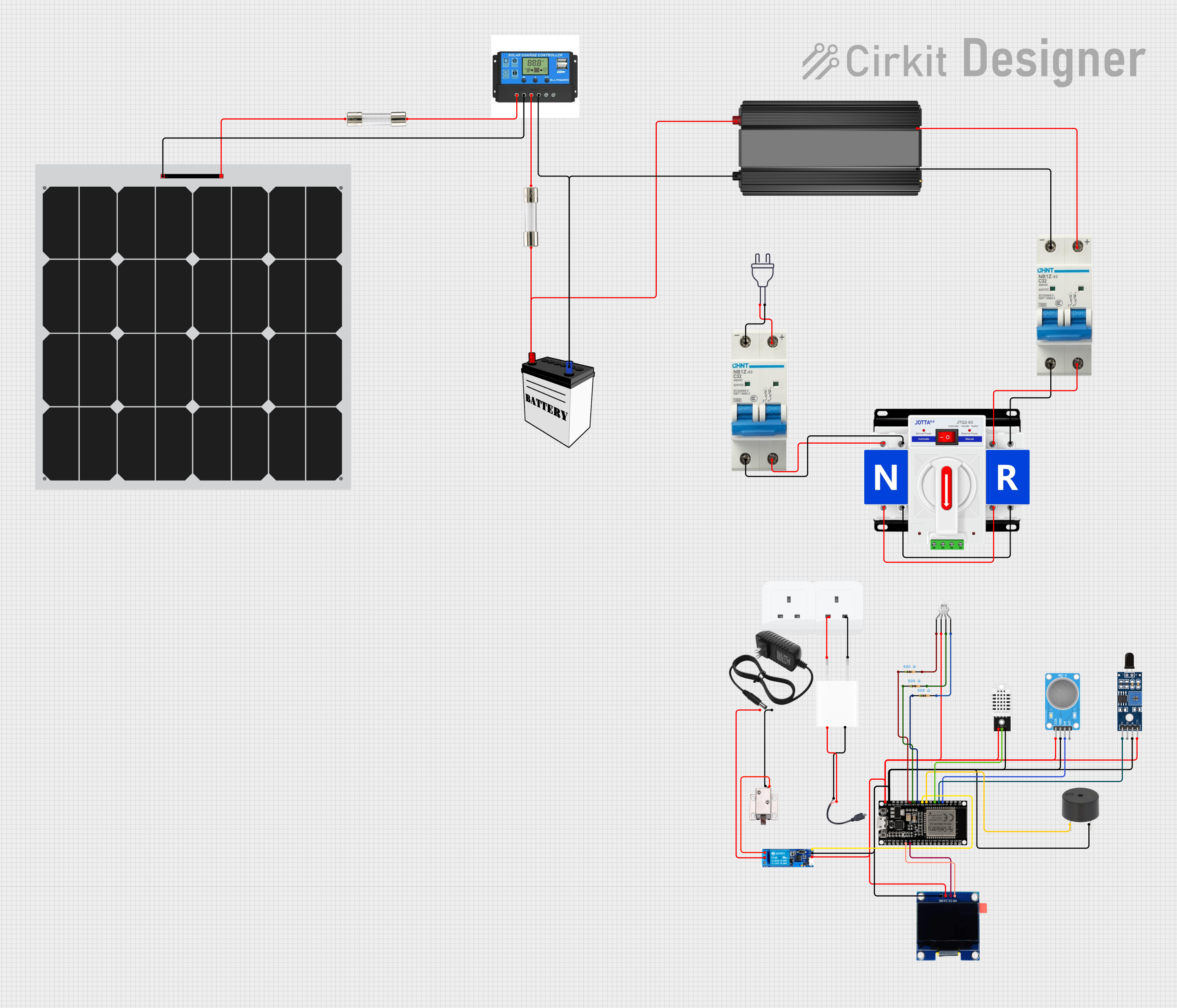

Explore Projects Built with 2P Breaker
Common Applications and Use Cases
- Protection of dual-phase electrical systems in residential, commercial, and industrial setups.
- Safeguarding motor circuits and other high-power equipment.
- Preventing damage to wiring and connected devices due to overcurrent or short circuits.
- Use in distribution boards and control panels for enhanced safety.
Technical Specifications
Below are the key technical details of the Schneider MCB F1-2 Motor:
| Parameter | Value |
|---|---|
| Manufacturer | Schneider |
| Part ID | MCB F1-2 Motor |
| Number of Poles | 2 |
| Rated Voltage | 240/415V AC |
| Rated Current | 1A to 63A (varies by model) |
| Breaking Capacity | 10 kA |
| Tripping Curve | B, C, or D (depending on model) |
| Frequency | 50/60 Hz |
| Mounting Type | DIN Rail |
| Operating Temperature | -25°C to +70°C |
| Standards Compliance | IEC 60898-1, IEC 60947-2 |
Pin Configuration and Descriptions
The 2P Breaker has two input terminals and two output terminals. Below is the pin configuration:
| Pin | Description |
|---|---|
| L1 IN | Line 1 input (phase 1) |
| L2 IN | Line 2 input (phase 2) |
| L1 OUT | Line 1 output (phase 1) |
| L2 OUT | Line 2 output (phase 2) |
Usage Instructions
How to Use the Component in a Circuit
- Mounting the Breaker: Secure the breaker onto a standard DIN rail in the distribution board or control panel.
- Wiring:
- Connect the incoming power supply to the L1 IN and L2 IN terminals.
- Connect the outgoing load (e.g., motor, appliances) to the L1 OUT and L2 OUT terminals.
- Ensure all connections are tight and secure to prevent arcing or loose contacts.
- Power On: Once the wiring is complete, switch on the breaker to allow current flow. The breaker will automatically trip in case of an overload or short circuit.
Important Considerations and Best Practices
- Select the Correct Rating: Choose a breaker with the appropriate current rating (e.g., 10A, 16A) based on the load requirements.
- Check Tripping Curve: Use a breaker with the correct tripping curve (B, C, or D) for the application:
- B Curve: For resistive loads (e.g., lighting).
- C Curve: For inductive loads (e.g., motors).
- D Curve: For high inrush current loads (e.g., transformers).
- Avoid Overloading: Do not exceed the rated current of the breaker to prevent nuisance tripping.
- Regular Maintenance: Periodically inspect the breaker for signs of wear, damage, or loose connections.
Arduino Integration
While the 2P Breaker is not directly connected to an Arduino, it can be used in circuits where the Arduino controls devices powered through the breaker. For example, an Arduino can control a relay that switches a motor protected by the breaker.
Here is an example Arduino code for controlling a motor via a relay:
// Example: Controlling a motor with a relay and protecting it with a 2P breaker

const int relayPin = 7; // Pin connected to the relay module

void setup() {
  pinMode(relayPin, OUTPUT); // Set relay pin as output
  digitalWrite(relayPin, LOW); // Ensure relay is off at startup
}

void loop() {
  // Turn on the motor
  digitalWrite(relayPin, HIGH); // Activate relay
  delay(5000); // Run motor for 5 seconds

  // Turn off the motor
  digitalWrite(relayPin, LOW); // Deactivate relay
  delay(5000); // Wait for 5 seconds before restarting
}
Note: Ensure the motor is connected to the breaker-protected circuit, and the relay is rated for the motor's current.
Troubleshooting and FAQs
Common Issues Users Might Face
Breaker Trips Frequently:
- Cause: Overloaded circuit or short circuit.
- Solution: Check the load current and ensure it does not exceed the breaker's rated current. Inspect the wiring for short circuits.
Breaker Does Not Trip During Overload:
- Cause: Faulty breaker or incorrect rating.
- Solution: Replace the breaker with a new one and verify the current rating matches the load.
Loose Connections:
- Cause: Improperly tightened terminals.
- Solution: Re-tighten all connections and ensure they are secure.
Breaker Does Not Reset:
- Cause: Persistent fault in the circuit.
- Solution: Identify and fix the fault (e.g., short circuit) before attempting to reset the breaker.
Solutions and Tips for Troubleshooting
- Use a multimeter to measure the current and voltage in the circuit to identify potential issues.
- Verify that the breaker is installed correctly and that the DIN rail is properly grounded.
- If the breaker trips immediately after resetting, disconnect the load and test the breaker with no load to isolate the issue.
By following this documentation, users can effectively install, use, and troubleshoot the Schneider MCB F1-2 Motor 2P Breaker in their electrical systems.