Cirkit Designer
Your all-in-one circuit design IDE
Home /
Component Documentation
How to Use green light 220vac: Examples, Pinouts, and Specs
Introduction
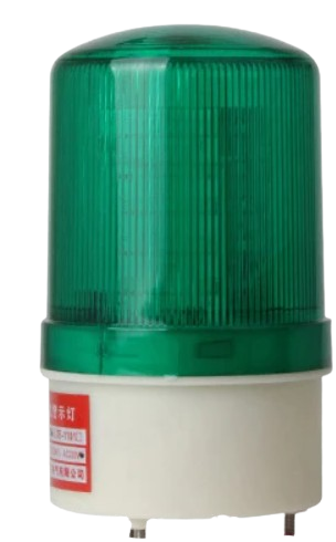
The Green Light Emitting Diode (LED) for 220VAC is an electronic component designed to emit green light when connected to a 220 volts alternating current (AC) supply. This LED is typically used as an indicator light in various electrical applications such as power strips, appliances, control panels, and other devices where visual confirmation of operation is necessary.
Explore Projects Built with green light 220vac
LED Indicator Circuit with Push Switches and Voltage Regulation

This circuit converts 220V AC to 24V DC using a power transformer and a bridge rectifier, then regulates the voltage to a stable output using a voltage regulator. It includes multiple LEDs controlled by push switches, with current limiting provided by a resistor.
220V AC Bulb Control Circuit with Rocker Switch
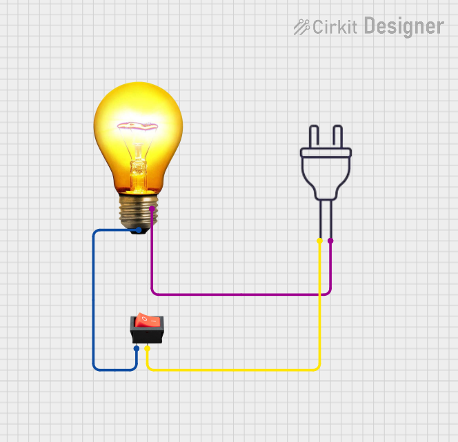
This circuit is a simple AC power control circuit designed to power an AC bulb using a 220V power source. It includes a rocker switch that acts as an on/off control for the bulb. When the switch is closed, it completes the circuit allowing current to flow through the bulb, thus turning it on.
ESP8266 NodeMCU Controlled SSR for Smart Power Management

This circuit features an ESP8266 NodeMCU microcontroller that controls a solid-state relay to switch a 120V fan and a red lamp on and off. A green LED is used as an indicator for the relay's operation, and the circuit is powered by a 220V AC power source connected through an IEC320 inlet.
Wi-Fi Enabled Motion-Activated Lighting System with Radar Sensor

This circuit is designed to control an AC LED bulb using a 220V power source, with an infrared motion sensor and an MMWave radar sensor providing input signals. The two-channel relay is used to switch the LED bulb on and off based on the sensor inputs, while the ESP8266 microcontroller is likely programmed to process the sensor data and control the relay. A converter is included to interface between the sensors, microcontroller, and the relay, ensuring proper voltage levels.
Explore Projects Built with green light 220vac
LED Indicator Circuit with Push Switches and Voltage Regulation
This circuit converts 220V AC to 24V DC using a power transformer and a bridge rectifier, then regulates the voltage to a stable output using a voltage regulator. It includes multiple LEDs controlled by push switches, with current limiting provided by a resistor.
220V AC Bulb Control Circuit with Rocker Switch
This circuit is a simple AC power control circuit designed to power an AC bulb using a 220V power source. It includes a rocker switch that acts as an on/off control for the bulb. When the switch is closed, it completes the circuit allowing current to flow through the bulb, thus turning it on.
ESP8266 NodeMCU Controlled SSR for Smart Power Management
This circuit features an ESP8266 NodeMCU microcontroller that controls a solid-state relay to switch a 120V fan and a red lamp on and off. A green LED is used as an indicator for the relay's operation, and the circuit is powered by a 220V AC power source connected through an IEC320 inlet.
Wi-Fi Enabled Motion-Activated Lighting System with Radar Sensor
This circuit is designed to control an AC LED bulb using a 220V power source, with an infrared motion sensor and an MMWave radar sensor providing input signals. The two-channel relay is used to switch the LED bulb on and off based on the sensor inputs, while the ESP8266 microcontroller is likely programmed to process the sensor data and control the relay. A converter is included to interface between the sensors, microcontroller, and the relay, ensuring proper voltage levels.
Common Applications and Use Cases
- Power status indicators on consumer electronics
- Signal lights in industrial control systems
- Illumination for switches and buttons
- Decorative lighting in architectural applications
Technical Specifications
Key Technical Details
- Nominal Operating Voltage: 220VAC
- Frequency: 50/60Hz
- Light Color: Green
- Luminous Intensity: Specified in millicandela (mcd), varies by model
- Power Consumption: Typically less than 2W
- Lifespan: Approximately 25,000 to 50,000 hours
Pin Configuration and Descriptions
| Pin Number | Description |
|---|---|
| 1 | Anode (AC Live) |
| 2 | Cathode (AC Neutral) |
Usage Instructions
How to Use the Component in a Circuit
- Identify the Pins: Determine the anode and cathode pins of the LED. The longer pin is usually the anode.
- Connect to AC Supply: Connect the anode to the live wire of the AC supply and the cathode to the neutral wire.
- Series Resistor: It is essential to use an appropriate current-limiting resistor or an LED driver designed for 220VAC to prevent damage to the LED.
- Insulation: Ensure all connections are properly insulated to prevent electrical shock.
Important Considerations and Best Practices
- Safety First: Always disconnect power before making any changes to the circuit.
- Heat Dissipation: Ensure adequate heat sinking if necessary, as high voltages can generate significant heat.
- Correct Polarity: Reversing the AC connections will not damage the LED, but it will not light up.
- Surge Protection: Use a surge protector to safeguard the LED against voltage spikes.
Troubleshooting and FAQs
Common Issues Users Might Face
- LED Not Lighting Up: Check the connections and ensure the LED is properly connected to the AC supply.
- Flickering LED: This may be due to voltage fluctuations. Verify the stability of the AC supply.
- Dim Light: The LED may be nearing the end of its lifespan or there may be issues with the current-limiting resistor.
Solutions and Tips for Troubleshooting
- Check Connections: Ensure all connections are secure and properly insulated.
- Replace LED: If the LED is dim or not working, consider replacing it.
- Voltage Check: Use a multimeter to verify the AC supply voltage is within the LED's operating range.
FAQs
- Q: Can I connect the LED directly to 220VAC without a resistor?
- A: No, you must use a current-limiting resistor or an LED driver to prevent damage to the LED.
- Q: Is it safe to touch the LED terminals when it's connected to the power supply?
- A: No, touching the terminals can result in an electric shock. Always ensure the power is off before handling the LED.
Example Code for Arduino UNO Connection
// Note: Direct connection of a 220VAC LED to an Arduino is not recommended
// and can be dangerous. This example assumes the use of a low-voltage LED
// with a relay module to control a 220VAC circuit.

#include <Arduino.h>

const int relayPin = 2; // Relay control connected to digital pin 2

void setup() {
  pinMode(relayPin, OUTPUT); // Initialize the relay pin as an output
}

void loop() {
  digitalWrite(relayPin, HIGH); // Turn on the relay (LED ON)
  delay(1000);                  // Wait for 1 second
  digitalWrite(relayPin, LOW);  // Turn off the relay (LED OFF)
  delay(1000);                  // Wait for 1 second
}
Note: The above code is for illustrative purposes only. A relay module rated for 220VAC should be used to control the high-voltage LED, and the Arduino can only be used to control the relay, not the LED directly. Always consult a professional electrician when dealing with high-voltage circuits.