Cirkit Designer Logo
Cirkit Designer
Your all-in-one circuit design IDE
Home / 
Component Documentation

How to Use Raspberry Pi Zero 2 W: Examples, Pinouts, and Specs
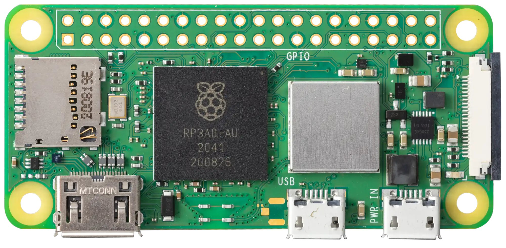

Image of Raspberry Pi Zero 2 W
Cirkit Designer LogoDesign with Raspberry Pi Zero 2 W in Cirkit Designer

Introduction

The Raspberry Pi Zero 2 W is a compact, low-cost single-board computer developed by Raspberry Pi. It features a quad-core ARM Cortex-A53 processor, 512MB of RAM, built-in Wi-Fi, Bluetooth, and a versatile set of GPIO pins for hardware interfacing. Despite its small size, the Zero 2 W is a powerful and energy-efficient platform suitable for a wide range of applications.

Explore Projects Built with Raspberry Pi Zero 2 W
Use Cirkit Designer to design, explore, and prototype these projects online. Some projects support real-time simulation. Click "Open Project" to start designing instantly!
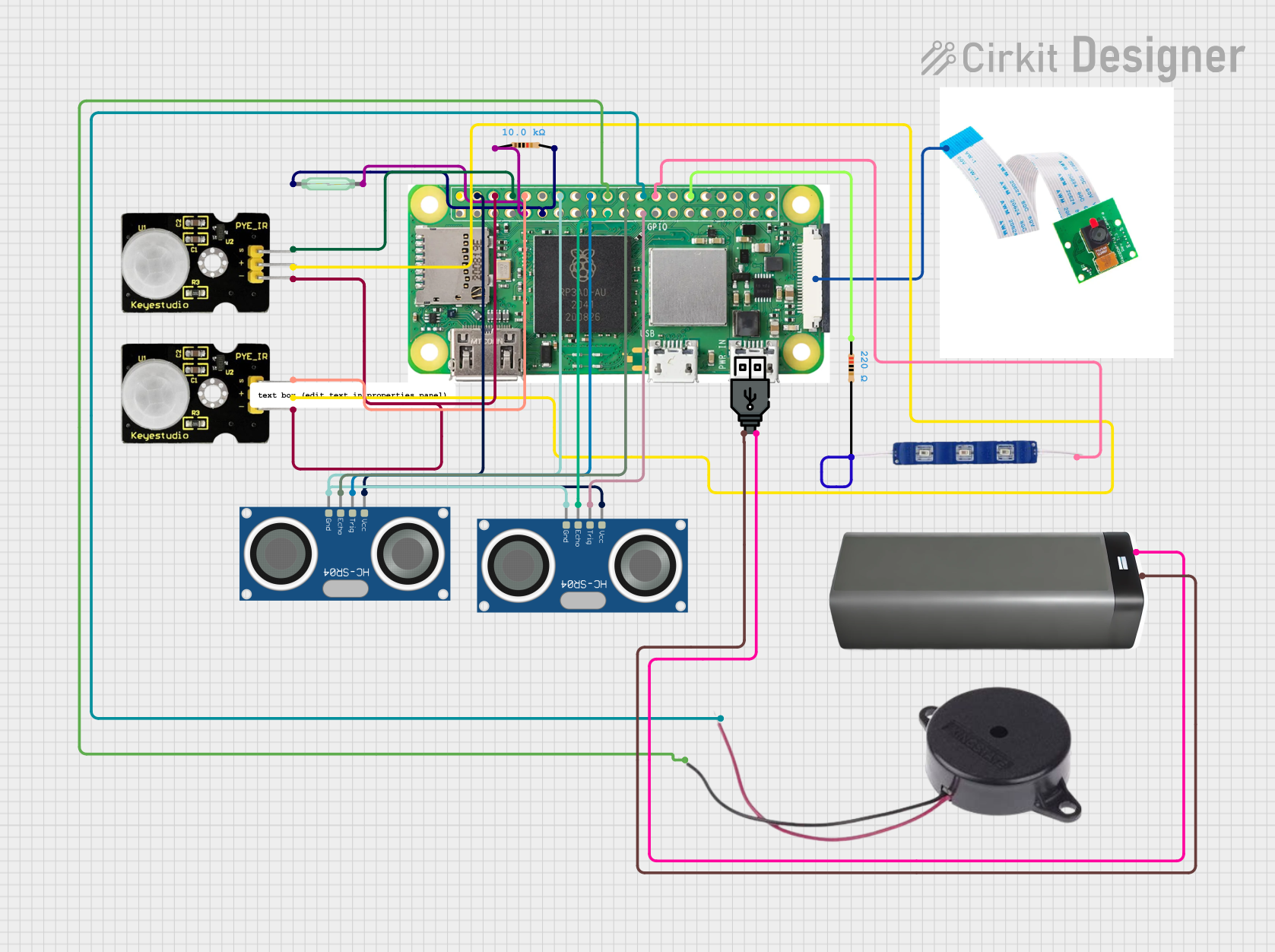
Raspberry Pi Zero W-Based Security System with PIR, Ultrasonic Sensors, and Camera
Image of electronic 2: A project utilizing Raspberry Pi Zero 2 W in a practical application
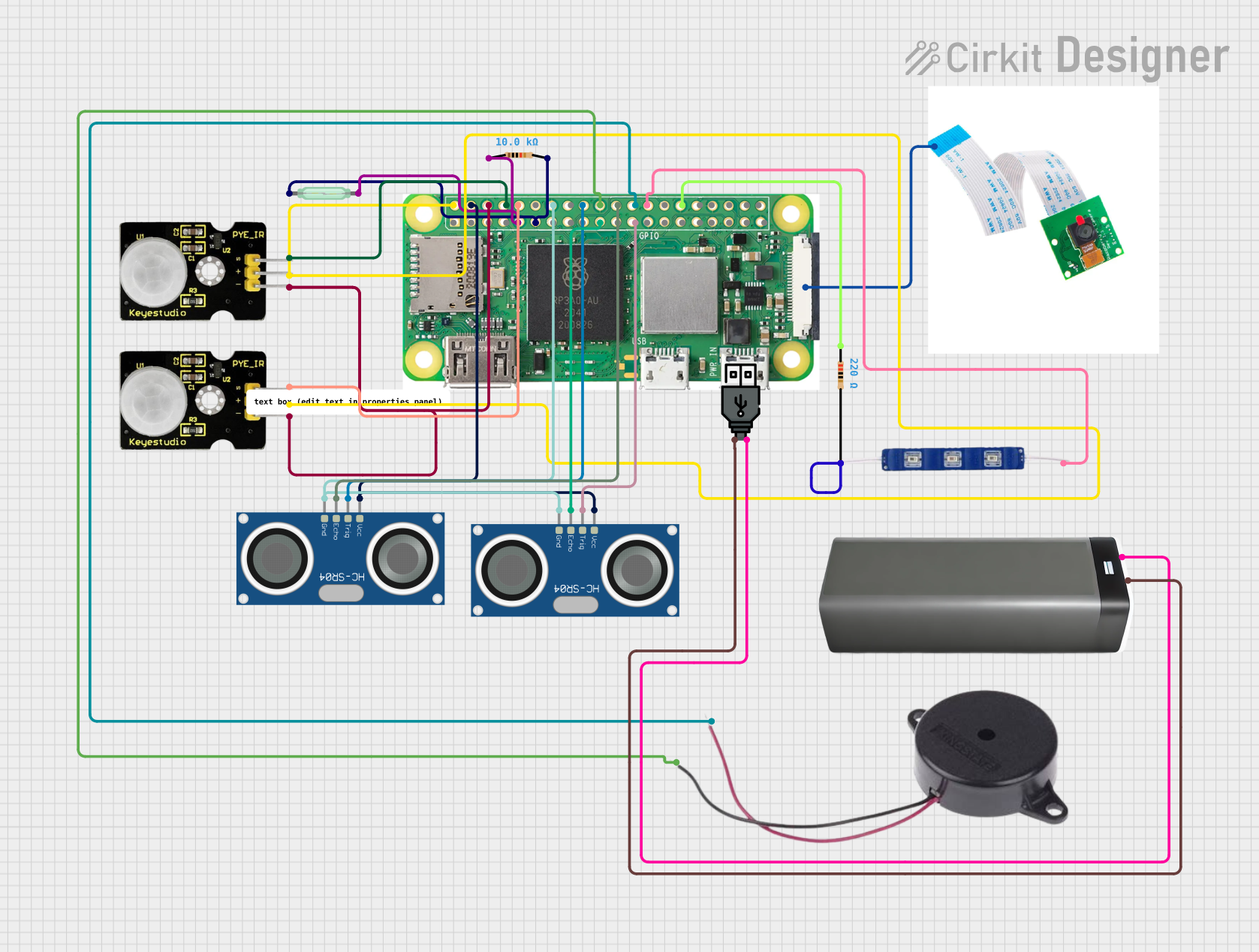
This circuit features a Raspberry Pi Zero W connected to various sensors and output devices. It includes two PIR sensors for motion detection, two HC-SR04 ultrasonic sensors for distance measurement, a reed switch for magnetic field detection, and a Raspberry Pi camera module. Additionally, the circuit has a buzzer for audible alerts and a 12V blue LED for visual indication, both controlled by the Raspberry Pi's GPIO pins. Power is supplied through a USB power connection linked to a battery pack.
Cirkit Designer LogoOpen Project in Cirkit Designer
Raspberry Pi Zero W-Based Security System with Motion Detection and Camera
Image of electronic 2: A project utilizing Raspberry Pi Zero 2 W in a practical application
This circuit is a Raspberry Pi Zero W-based security system equipped with two PIR sensors for motion detection, two HC-SR04 ultrasonic sensors for distance measurement, a reed switch for magnetic field detection, and a Raspberry Pi camera module for visual monitoring. It also includes a buzzer and a 12V blue LED for audio-visual alerts. The system is powered through a USB power connection linked to a battery pack, and the Raspberry Pi is programmed to control the sensors and output signals based on detected motion, distance changes, or magnetic field presence.
Cirkit Designer LogoOpen Project in Cirkit Designer
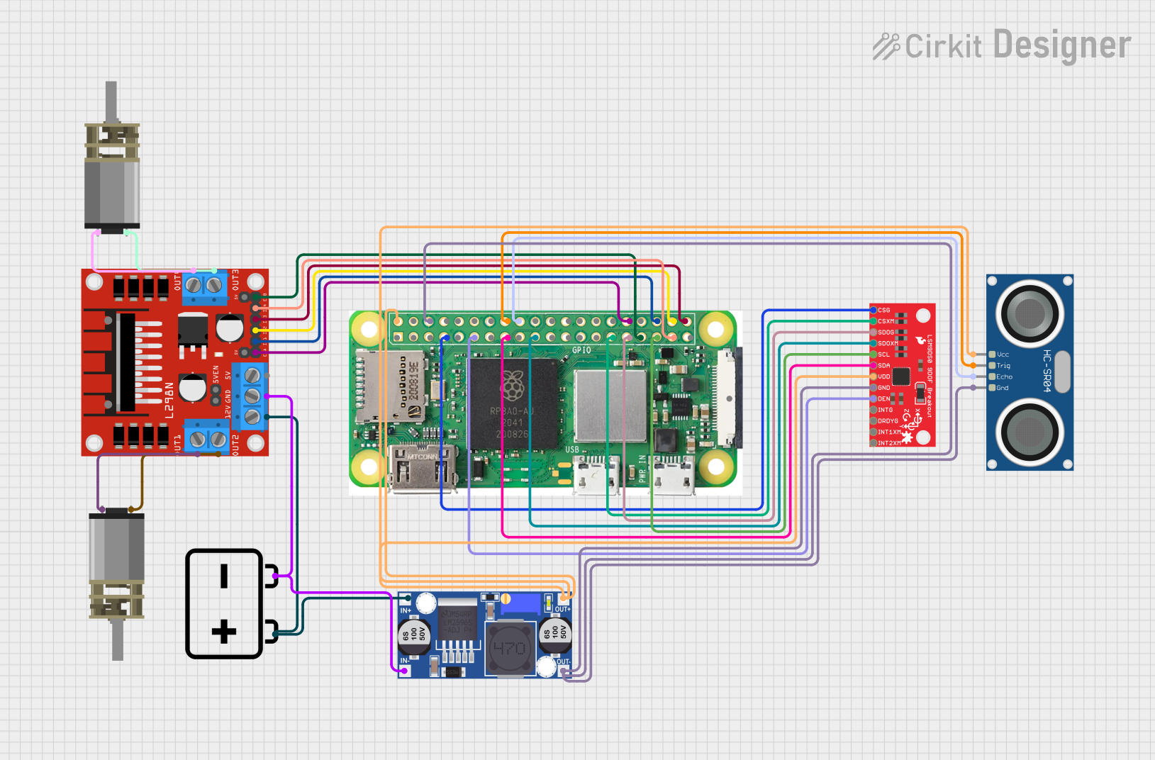
Raspberry Pi Zero W Controlled Robotic Vehicle with Ultrasonic Navigation and 9DOF Sensor Feedback
Image of line follower : A project utilizing Raspberry Pi Zero 2 W in a practical application
This circuit features a Raspberry Pi Zero W as the central controller, interfaced with an HC-SR04 ultrasonic sensor for distance measurement, a 9DOF sensor LSM9DS0 for motion tracking, and two DC Mini Metal Gear Motors driven by an L298N motor driver for actuation. The motors are powered by a 12V battery, with a buck converter regulating voltage for the Raspberry Pi and sensors. The Raspberry Pi manages sensor data processing and motor control, likely for a mobile robot or a similar automated system.
Cirkit Designer LogoOpen Project in Cirkit Designer
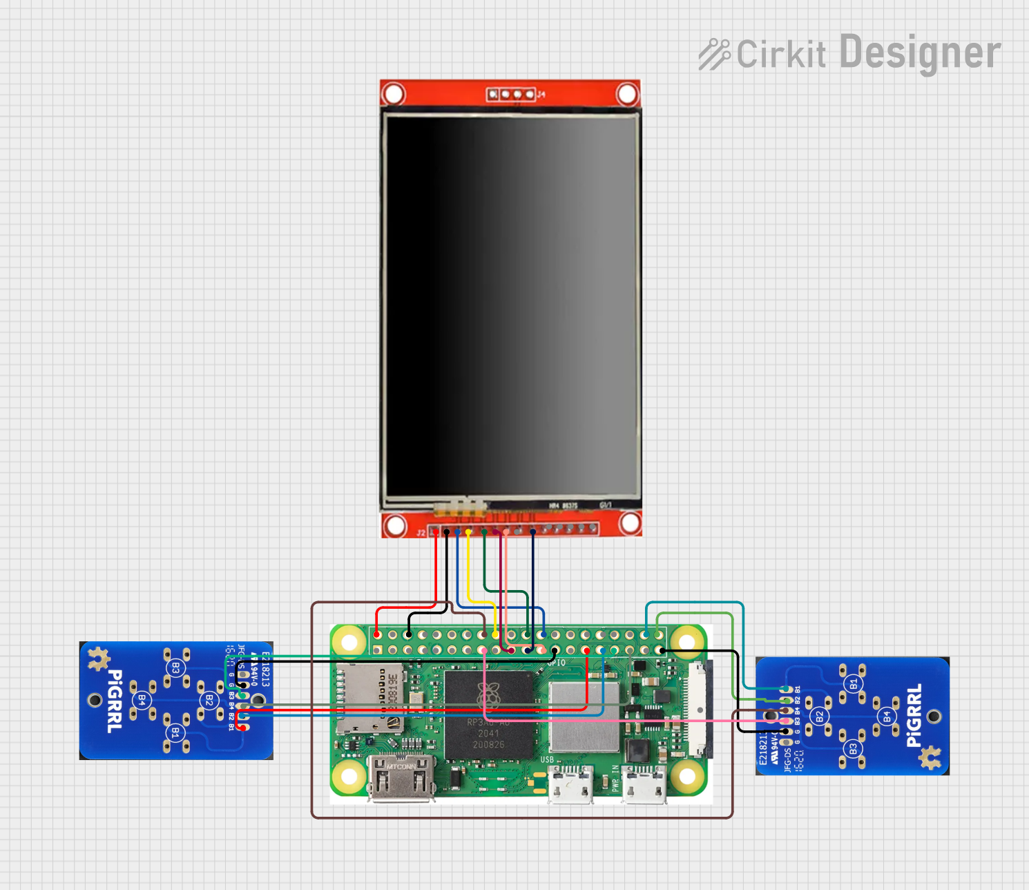
Raspberry Pi Zero W-Based Handheld Gaming Console with LCD Display
Image of pigame: A project utilizing Raspberry Pi Zero 2 W in a practical application
This circuit integrates a Raspberry Pi Zero W with an LCD TFT screen and two custom PiGrrl Zero gamepad PCBs. The Raspberry Pi provides power to the LCD screen and communicates with it via GPIO pins for control signals and SPI for data transfer. The gamepad PCBs are connected to the Raspberry Pi's GPIO pins, allowing for user input to be processed by the Raspberry Pi for gaming or other interactive applications.
Cirkit Designer LogoOpen Project in Cirkit Designer

Explore Projects Built with Raspberry Pi Zero 2 W

Use Cirkit Designer to design, explore, and prototype these projects online. Some projects support real-time simulation. Click "Open Project" to start designing instantly!
Image of electronic 2: A project utilizing Raspberry Pi Zero 2 W in a practical application
Raspberry Pi Zero W-Based Security System with PIR, Ultrasonic Sensors, and Camera
This circuit features a Raspberry Pi Zero W connected to various sensors and output devices. It includes two PIR sensors for motion detection, two HC-SR04 ultrasonic sensors for distance measurement, a reed switch for magnetic field detection, and a Raspberry Pi camera module. Additionally, the circuit has a buzzer for audible alerts and a 12V blue LED for visual indication, both controlled by the Raspberry Pi's GPIO pins. Power is supplied through a USB power connection linked to a battery pack.
Cirkit Designer LogoOpen Project in Cirkit Designer
Image of electronic 2: A project utilizing Raspberry Pi Zero 2 W in a practical application
Raspberry Pi Zero W-Based Security System with Motion Detection and Camera
This circuit is a Raspberry Pi Zero W-based security system equipped with two PIR sensors for motion detection, two HC-SR04 ultrasonic sensors for distance measurement, a reed switch for magnetic field detection, and a Raspberry Pi camera module for visual monitoring. It also includes a buzzer and a 12V blue LED for audio-visual alerts. The system is powered through a USB power connection linked to a battery pack, and the Raspberry Pi is programmed to control the sensors and output signals based on detected motion, distance changes, or magnetic field presence.
Cirkit Designer LogoOpen Project in Cirkit Designer
Image of line follower : A project utilizing Raspberry Pi Zero 2 W in a practical application
Raspberry Pi Zero W Controlled Robotic Vehicle with Ultrasonic Navigation and 9DOF Sensor Feedback
This circuit features a Raspberry Pi Zero W as the central controller, interfaced with an HC-SR04 ultrasonic sensor for distance measurement, a 9DOF sensor LSM9DS0 for motion tracking, and two DC Mini Metal Gear Motors driven by an L298N motor driver for actuation. The motors are powered by a 12V battery, with a buck converter regulating voltage for the Raspberry Pi and sensors. The Raspberry Pi manages sensor data processing and motor control, likely for a mobile robot or a similar automated system.
Cirkit Designer LogoOpen Project in Cirkit Designer
Image of pigame: A project utilizing Raspberry Pi Zero 2 W in a practical application
Raspberry Pi Zero W-Based Handheld Gaming Console with LCD Display
This circuit integrates a Raspberry Pi Zero W with an LCD TFT screen and two custom PiGrrl Zero gamepad PCBs. The Raspberry Pi provides power to the LCD screen and communicates with it via GPIO pins for control signals and SPI for data transfer. The gamepad PCBs are connected to the Raspberry Pi's GPIO pins, allowing for user input to be processed by the Raspberry Pi for gaming or other interactive applications.
Cirkit Designer LogoOpen Project in Cirkit Designer

Common Applications and Use Cases

  • IoT (Internet of Things) devices and smart home automation
  • Portable and embedded systems
  • Robotics and sensor interfacing
  • Media streaming and playback
  • Educational projects and prototyping
  • Retro gaming emulation

Technical Specifications

Key Technical Details

Specification Details
Processor Quad-core ARM Cortex-A53, 1 GHz
RAM 512MB LPDDR2
Wireless Connectivity 802.11 b/g/n Wi-Fi, Bluetooth 4.2, BLE
GPIO 40-pin GPIO header (unpopulated)
USB Ports 1x Micro-USB for data, 1x Micro-USB for power
Video Output Mini HDMI (1080p60 supported)
Storage MicroSD card slot
Power Supply 5V/2.5A via Micro-USB
Dimensions 65mm x 30mm x 5mm
Weight 9g

Pin Configuration and Descriptions

The Raspberry Pi Zero 2 W features a 40-pin GPIO header. Below is a summary of the pin configuration:

Pin Number Pin Name Functionality
1 3.3V Power 3.3V power supply
2 5V Power 5V power supply
3 GPIO2 (SDA1) I2C Data
4 5V Power 5V power supply
5 GPIO3 (SCL1) I2C Clock
6 Ground Ground
7 GPIO4 General-purpose I/O
8 GPIO14 (TXD) UART Transmit
9 Ground Ground
10 GPIO15 (RXD) UART Receive
... ... ... (Refer to the official GPIO pinout)

For the full GPIO pinout, refer to the official Raspberry Pi documentation.

Usage Instructions

How to Use the Raspberry Pi Zero 2 W in a Circuit

  1. Powering the Board: Use a 5V/2.5A power supply connected via the Micro-USB power port.
  2. Connecting Peripherals: Attach a keyboard, mouse, and monitor using a USB OTG adapter and Mini HDMI cable.
  3. Booting the OS: Flash a compatible operating system (e.g., Raspberry Pi OS) onto a MicroSD card and insert it into the MicroSD card slot.
  4. GPIO Interfacing: Use the 40-pin GPIO header to connect sensors, actuators, or other hardware. Ensure proper voltage levels to avoid damage.
  5. Wireless Connectivity: Configure Wi-Fi and Bluetooth through the operating system for remote access and communication.

Important Considerations and Best Practices

  • Power Supply: Always use a reliable 5V/2.5A power supply to ensure stable operation.
  • Static Protection: Handle the board with care to avoid electrostatic discharge (ESD) damage.
  • GPIO Voltage Levels: The GPIO pins operate at 3.3V logic levels. Avoid applying 5V directly to the GPIO pins.
  • Cooling: For intensive tasks, consider adding a heatsink to prevent overheating.

Example: Blinking an LED with GPIO and Python

The following example demonstrates how to blink an LED connected to GPIO17 (pin 11) using Python:


Import the GPIO and time libraries

import RPi.GPIO as GPIO import time

Set up GPIO mode and pin

GPIO.setmode(GPIO.BCM) # Use Broadcom pin numbering GPIO.setup(17, GPIO.OUT) # Set GPIO17 as an output pin

try: while True: GPIO.output(17, GPIO.HIGH) # Turn LED on time.sleep(1) # Wait for 1 second GPIO.output(17, GPIO.LOW) # Turn LED off time.sleep(1) # Wait for 1 second except KeyboardInterrupt: # Clean up GPIO settings on exit GPIO.cleanup()


Using with Arduino UNO

The Raspberry Pi Zero 2 W can communicate with an Arduino UNO via serial communication. Use the UART pins (GPIO14 and GPIO15) for this purpose. Ensure proper voltage level shifting if required.

Troubleshooting and FAQs

Common Issues and Solutions

  1. The board does not boot:

    • Ensure the MicroSD card is properly inserted and contains a valid OS image.
    • Verify the power supply provides sufficient current (5V/2.5A).
  2. Wi-Fi connectivity issues:

    • Check the Wi-Fi credentials and ensure the network is within range.
    • Update the operating system to the latest version for improved wireless performance.
  3. GPIO pins not working:

    • Confirm the correct GPIO pin numbering (BCM vs. physical pin numbers).
    • Check for loose connections or incorrect wiring.
  4. Overheating:

    • Add a heatsink or improve ventilation if the board overheats during intensive tasks.

FAQs

  • Can I power the Raspberry Pi Zero 2 W via GPIO pins? Yes, you can power the board using the 5V and GND pins on the GPIO header, but this bypasses the onboard power protection circuitry.

  • What operating systems are compatible with the Raspberry Pi Zero 2 W? The board supports Raspberry Pi OS, Ubuntu, and other lightweight Linux distributions.

  • Can I use the Raspberry Pi Zero 2 W for AI/ML projects? Yes, lightweight AI/ML tasks can be performed using frameworks like TensorFlow Lite or Edge Impulse.

  • Does the Raspberry Pi Zero 2 W support USB boot? No, the Raspberry Pi Zero 2 W does not support USB boot. It requires a MicroSD card for booting.

For additional support, refer to the official Raspberry Pi documentation and forums.