
How to Use ESP32 WROOM-32U: Examples, Pinouts, and Specs
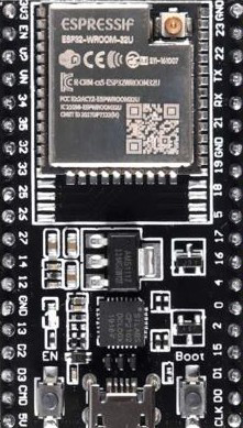
 Design with ESP32 WROOM-32U in Cirkit Designer
Introduction
The ESP32 WROOM-32U, manufactured by Espressif, is a powerful Wi-Fi and Bluetooth microcontroller module designed for IoT applications and embedded systems. It features dual-core processing capabilities, making it suitable for high-performance tasks while maintaining energy efficiency. The module is equipped with an external antenna connector, providing enhanced wireless range and flexibility in antenna selection.
Explore Projects Built with ESP32 WROOM-32U
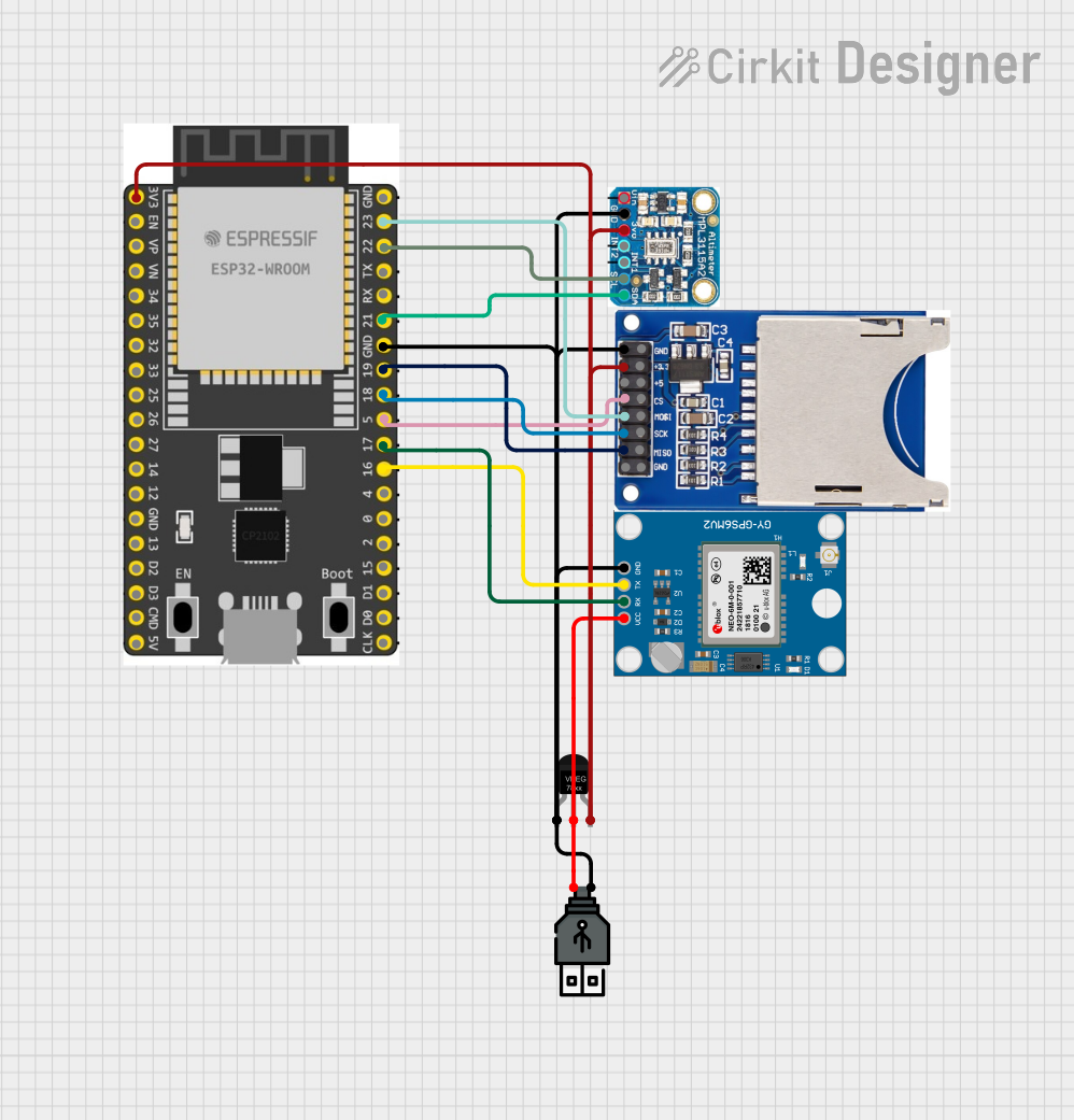 Open Project in Cirkit Designer
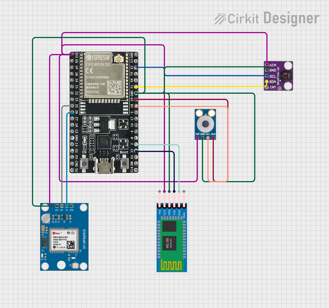 Open Project in Cirkit Designer
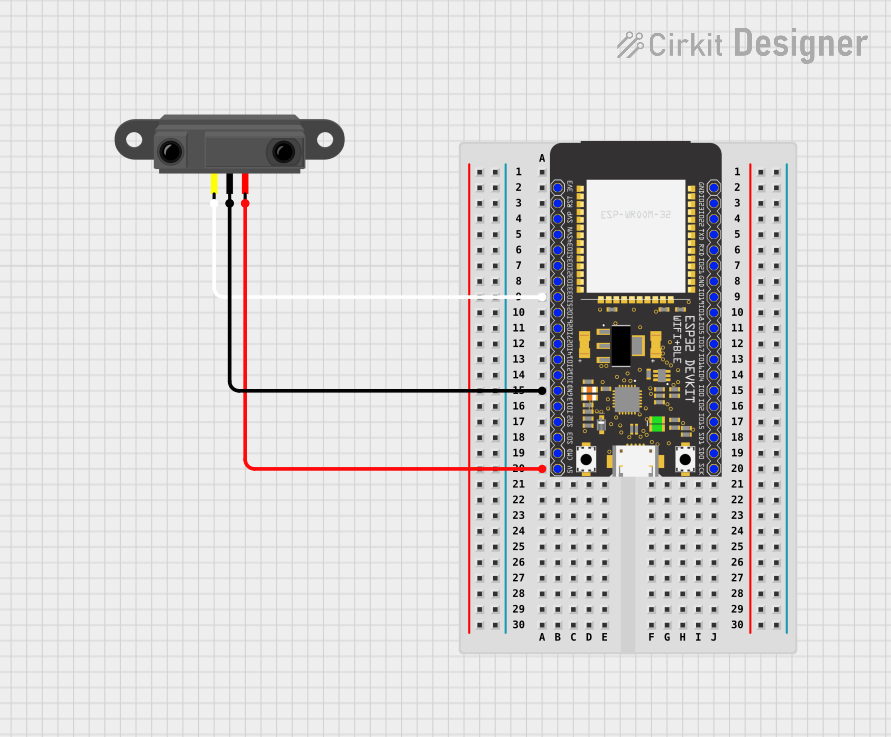 Open Project in Cirkit Designer
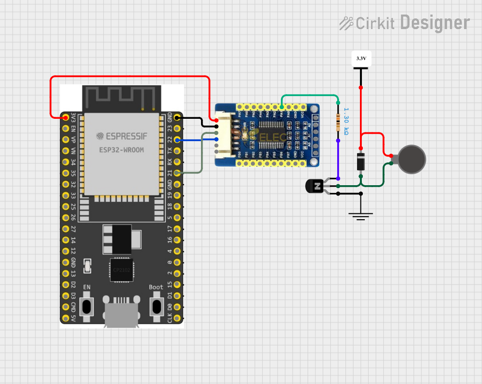 Open Project in Cirkit Designer
Explore Projects Built with ESP32 WROOM-32U
Open Project in Cirkit DesignerOpen Project in Cirkit DesignerOpen Project in Cirkit DesignerOpen Project in Cirkit DesignerCommon Applications
- Internet of Things (IoT) devices
- Smart home automation systems
- Wearable electronics
- Wireless sensor networks
- Industrial automation
- Robotics and drones
- Audio streaming and Bluetooth-enabled devices
Technical Specifications
Key Technical Details
| Parameter | Specification |
|---|---|
| Manufacturer | Espressif |
| Part ID | WROOM-32U |
| Microcontroller | ESP32-D0WD |
| Core Architecture | Dual-core Xtensa® 32-bit LX6 |
| Clock Speed | Up to 240 MHz |
| Wireless Connectivity | Wi-Fi 802.11 b/g/n (2.4 GHz), Bluetooth v4.2 BR/EDR and BLE |
| Flash Memory | 4 MB (external SPI flash) |
| SRAM | 520 KB |
| Operating Voltage | 3.0V to 3.6V |
| GPIO Pins | 34 |
| Antenna | External antenna via U.FL connector |
| Operating Temperature | -40°C to +85°C |
| Power Consumption | Ultra-low power consumption in deep sleep mode |
Pin Configuration and Descriptions
The ESP32 WROOM-32U module has 38 pins. Below is a summary of the key pins and their functions:
| Pin Number | Pin Name | Function Description |
|---|---|---|
| 1 | EN | Enable pin. Active high to enable the module. |
| 2 | IO0 | GPIO0, used for boot mode selection. |
| 3 | IO2 | GPIO2, general-purpose I/O. |
| 4 | IO4 | GPIO4, general-purpose I/O. |
| 5 | IO5 | GPIO5, general-purpose I/O. |
| 6 | IO12 | GPIO12, general-purpose I/O. |
| 7 | IO13 | GPIO13, general-purpose I/O. |
| 8 | IO14 | GPIO14, general-purpose I/O. |
| 9 | IO15 | GPIO15, general-purpose I/O. |
| 10 | IO16 | GPIO16, general-purpose I/O. |
| 11 | IO17 | GPIO17, general-purpose I/O. |
| 12 | IO18 | GPIO18, general-purpose I/O. |
| 13 | IO19 | GPIO19, general-purpose I/O. |
| 14 | IO21 | GPIO21, general-purpose I/O. |
| 15 | IO22 | GPIO22, general-purpose I/O. |
| 16 | IO23 | GPIO23, general-purpose I/O. |
| 17 | GND | Ground |
| 18 | 3V3 | 3.3V power supply |
| 19 | TXD0 | UART0 transmit pin |
| 20 | RXD0 | UART0 receive pin |
For a complete pinout, refer to the official datasheet.
Usage Instructions
How to Use the ESP32 WROOM-32U in a Circuit
- Power Supply: Provide a stable 3.3V power supply to the module. Ensure the power source can handle the peak current requirements (up to 500 mA).
- Antenna: Connect an external antenna to the U.FL connector for optimal wireless performance.
- Boot Mode: To upload code, connect GPIO0 to GND during reset to enter bootloader mode.
- Connections: Use UART pins (TXD0 and RXD0) for serial communication with a computer or microcontroller.
- Programming: The module can be programmed using the Arduino IDE, ESP-IDF, or other compatible environments.
Important Considerations and Best Practices
- Use level shifters if interfacing with 5V logic devices, as the ESP32 operates at 3.3V logic levels.
- Decouple the power supply with capacitors (e.g., 10 µF and 0.1 µF) close to the module's power pins to reduce noise.
- Ensure proper grounding to avoid signal interference.
- Use an appropriate external antenna for your application to maximize wireless range.
Example Code for Arduino UNO
Below is an example of how to use the ESP32 WROOM-32U with an Arduino UNO to blink an LED connected to GPIO2:
// Include the WiFi library for ESP32
#include <WiFi.h>

// Define the GPIO pin for the LED
#define LED_PIN 2

void setup() {
  // Initialize the LED pin as an output
  pinMode(LED_PIN, OUTPUT);

  // Start the serial communication
  Serial.begin(115200);
  Serial.println("ESP32 WROOM-32U LED Blink Example");
}

void loop() {
  // Turn the LED on
  digitalWrite(LED_PIN, HIGH);
  Serial.println("LED is ON");
  delay(1000); // Wait for 1 second

  // Turn the LED off
  digitalWrite(LED_PIN, LOW);
  Serial.println("LED is OFF");
  delay(1000); // Wait for 1 second
}
Troubleshooting and FAQs
Common Issues and Solutions
Module Not Responding
- Ensure the module is powered with a stable 3.3V supply.
- Check the connections, especially the EN pin (should be pulled high).
Wi-Fi Connection Fails
- Verify the SSID and password in your code.
- Ensure the external antenna is properly connected.
Code Upload Fails
- Check that GPIO0 is connected to GND during reset for bootloader mode.
- Ensure the correct COM port and board are selected in the Arduino IDE.
Overheating
- Verify that the module is not drawing excessive current.
- Ensure proper ventilation and avoid short circuits.
FAQs
Q: Can the ESP32 WROOM-32U operate on 5V?
A: No, the module operates at 3.3V. Use a voltage regulator or level shifter for 5V systems.
Q: What is the maximum wireless range?
A: The range depends on the external antenna used. With a high-gain antenna, it can exceed 100 meters in open spaces.
Q: Can I use the ESP32 WROOM-32U for Bluetooth audio streaming?
A: Yes, the module supports Bluetooth Classic and BLE, making it suitable for audio streaming applications.
Q: How do I reset the module?
A: Pull the EN pin low momentarily to reset the module.
For further details, refer to the official Espressif documentation.