Cirkit Designer Logo
Cirkit Designer
Your all-in-one circuit design IDE
Home / 
Component Documentation

How to Use ESP32: Examples, Pinouts, and Specs

Image of ESP32
Cirkit Designer LogoDesign with ESP32 in Cirkit Designer

Introduction

The ESP32 is a powerful, low-cost microcontroller with integrated Wi-Fi and Bluetooth capabilities, making it an ideal choice for Internet of Things (IoT) applications and embedded systems. It is designed to provide high performance, low power consumption, and versatile connectivity options. The ESP32 is widely used in smart home devices, wearable electronics, industrial automation, and wireless sensor networks.

Explore Projects Built with ESP32

Use Cirkit Designer to design, explore, and prototype these projects online. Some projects support real-time simulation. Click "Open Project" to start designing instantly!
ESP32-Based Sensor Monitoring System with OLED Display and E-Stop
Image of MVP_design: A project utilizing ESP32 in a practical application
This circuit features an ESP32 microcontroller that interfaces with a variety of sensors and output devices. It is powered by a Lipo battery through a buck converter, ensuring a stable voltage supply. The ESP32 collects data from a DHT11 temperature and humidity sensor and a vibration sensor, controls a buzzer, and displays information on an OLED screen. An emergency stop (E Stop) is connected for safety purposes, allowing the system to be quickly deactivated.
Cirkit Designer LogoOpen Project in Cirkit Designer
ESP32-Based NTP Clock with DHT22 Temperature Sensor and WS2812 LED Matrix Display
Image of date time and temperature display : A project utilizing ESP32 in a practical application
This circuit features an ESP32 Devkit V1 microcontroller connected to a DHT22 temperature and humidity sensor and an 8x8 WS2812 RGB LED matrix. The ESP32 reads temperature data from the DHT22 sensor and displays the current date, time, and temperature on the LED matrix, with date and time synchronized via NTP (Network Time Protocol). The ESP32 provides power to both the DHT22 and the LED matrix and communicates with the DHT22 via GPIO 4 and with the LED matrix via GPIO 5.
Cirkit Designer LogoOpen Project in Cirkit Designer
ESP32-Based Environmental Monitoring System with Water Flow Sensing
Image of Water: A project utilizing ESP32 in a practical application
This circuit features an ESP32 Devkit V1 microcontroller connected to a DHT22 temperature and humidity sensor and a water flow sensor. The ESP32 reads environmental data from the DHT22 via a digital input pin (D33) and monitors water flow through the water flow sensor connected to another digital input pin (D23). The ESP32 is powered through its VIN pin, and both sensors are powered by the ESP32's 3V3 output, with common ground connections.
Cirkit Designer LogoOpen Project in Cirkit Designer
ESP32-Based Smart Weather Station with Wi-Fi Connectivity
Image of flowchart 3D: A project utilizing ESP32 in a practical application
This circuit features an ESP32 microcontroller interfacing with various sensors and modules, including a DHT22 temperature and humidity sensor, an ESP32 CAM for image capture, an I2C LCD screen for display, a load cell with an HX711 interface for weight measurement, and a buzzer for audio alerts. The ESP32 handles data acquisition, processing, and communication with these peripherals to create a multi-functional monitoring and alert system.
Cirkit Designer LogoOpen Project in Cirkit Designer

Explore Projects Built with ESP32

Use Cirkit Designer to design, explore, and prototype these projects online. Some projects support real-time simulation. Click "Open Project" to start designing instantly!
Image of MVP_design: A project utilizing ESP32 in a practical application
ESP32-Based Sensor Monitoring System with OLED Display and E-Stop
This circuit features an ESP32 microcontroller that interfaces with a variety of sensors and output devices. It is powered by a Lipo battery through a buck converter, ensuring a stable voltage supply. The ESP32 collects data from a DHT11 temperature and humidity sensor and a vibration sensor, controls a buzzer, and displays information on an OLED screen. An emergency stop (E Stop) is connected for safety purposes, allowing the system to be quickly deactivated.
Cirkit Designer LogoOpen Project in Cirkit Designer
Image of date time and temperature display : A project utilizing ESP32 in a practical application
ESP32-Based NTP Clock with DHT22 Temperature Sensor and WS2812 LED Matrix Display
This circuit features an ESP32 Devkit V1 microcontroller connected to a DHT22 temperature and humidity sensor and an 8x8 WS2812 RGB LED matrix. The ESP32 reads temperature data from the DHT22 sensor and displays the current date, time, and temperature on the LED matrix, with date and time synchronized via NTP (Network Time Protocol). The ESP32 provides power to both the DHT22 and the LED matrix and communicates with the DHT22 via GPIO 4 and with the LED matrix via GPIO 5.
Cirkit Designer LogoOpen Project in Cirkit Designer
Image of Water: A project utilizing ESP32 in a practical application
ESP32-Based Environmental Monitoring System with Water Flow Sensing
This circuit features an ESP32 Devkit V1 microcontroller connected to a DHT22 temperature and humidity sensor and a water flow sensor. The ESP32 reads environmental data from the DHT22 via a digital input pin (D33) and monitors water flow through the water flow sensor connected to another digital input pin (D23). The ESP32 is powered through its VIN pin, and both sensors are powered by the ESP32's 3V3 output, with common ground connections.
Cirkit Designer LogoOpen Project in Cirkit Designer
Image of flowchart 3D: A project utilizing ESP32 in a practical application
ESP32-Based Smart Weather Station with Wi-Fi Connectivity
This circuit features an ESP32 microcontroller interfacing with various sensors and modules, including a DHT22 temperature and humidity sensor, an ESP32 CAM for image capture, an I2C LCD screen for display, a load cell with an HX711 interface for weight measurement, and a buzzer for audio alerts. The ESP32 handles data acquisition, processing, and communication with these peripherals to create a multi-functional monitoring and alert system.
Cirkit Designer LogoOpen Project in Cirkit Designer

Technical Specifications

The ESP32 is packed with features that make it suitable for a wide range of applications. Below are its key technical specifications:

General Specifications

  • Processor: Dual-core Xtensa® 32-bit LX6 microprocessor
  • Clock Speed: Up to 240 MHz
  • RAM: 520 KB SRAM
  • Flash Memory: Typically 4 MB (varies by module)
  • Wi-Fi: 802.11 b/g/n (2.4 GHz)
  • Bluetooth: v4.2 BR/EDR and BLE
  • Operating Voltage: 3.3V
  • GPIO Pins: 34 (multipurpose)
  • ADC Channels: 18 (12-bit resolution)
  • DAC Channels: 2 (8-bit resolution)
  • PWM Channels: 16
  • I2C, SPI, UART: Supported
  • Power Consumption: Ultra-low power modes available

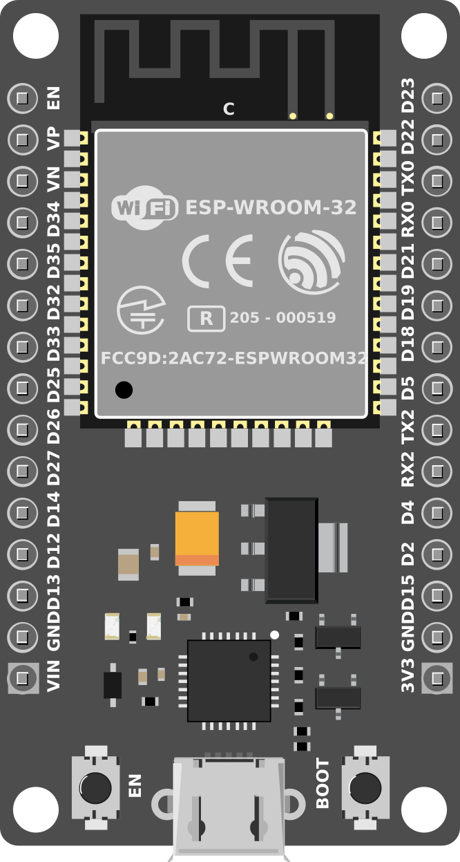
Pin Configuration and Descriptions

The ESP32 has a variety of pins for different functionalities. Below is a table summarizing the key pins:

Pin Name Function Description
GPIO0 Input/Output, Boot Mode Select Used for general I/O or to select boot mode during startup.
GPIO2 Input/Output, ADC, PWM General-purpose I/O, supports ADC and PWM functionalities.
GPIO12 Input/Output, ADC, Touch General-purpose I/O, supports ADC and capacitive touch sensing.
GPIO13 Input/Output, ADC, Touch General-purpose I/O, supports ADC and capacitive touch sensing.
GPIO15 Input/Output, ADC, PWM General-purpose I/O, supports ADC and PWM functionalities.
EN Enable Active high pin to enable or reset the chip.
3V3 Power Supply Provides 3.3V power output.
GND Ground Ground connection.
TX0 (GPIO1) UART Transmit UART0 transmit pin for serial communication.
RX0 (GPIO3) UART Receive UART0 receive pin for serial communication.

Note: The ESP32 has many GPIO pins, and their functionality can be configured via software. Refer to the datasheet for a complete pinout.

Usage Instructions

The ESP32 is versatile and can be used in a variety of circuits. Below are the steps to get started:

Basic Setup

  1. Power the ESP32: Connect the 3.3V and GND pins to a suitable power source. Avoid exceeding 3.6V to prevent damage.
  2. Connect to a Computer: Use a USB-to-serial adapter or a development board with a built-in USB interface.
  3. Install Drivers: Ensure the appropriate USB drivers for the ESP32 are installed on your computer.
  4. Install Development Environment:
    • Download and install the Arduino IDE or ESP-IDF (Espressif IoT Development Framework).
    • Add the ESP32 board support package to the Arduino IDE via the Board Manager.

Example: Blinking an LED

Below is an example of how to blink an LED connected to GPIO2 using the Arduino IDE:

// Define the GPIO pin where the LED is connected
#define LED_PIN 2

void setup() {
  pinMode(LED_PIN, OUTPUT); // Set GPIO2 as an output pin
}

void loop() {
  digitalWrite(LED_PIN, HIGH); // Turn the LED on
  delay(1000);                 // Wait for 1 second
  digitalWrite(LED_PIN, LOW);  // Turn the LED off
  delay(1000);                 // Wait for 1 second
}

Important Considerations

  • Voltage Levels: Ensure all connected peripherals operate at 3.3V logic levels. Use level shifters if necessary.
  • Boot Mode: GPIO0 must be pulled low during startup to enter programming mode.
  • Power Supply: Use a stable power source to avoid unexpected resets or malfunctions.

Troubleshooting and FAQs

Common Issues

  1. ESP32 Not Detected by Computer:

    • Ensure the correct USB drivers are installed.
    • Check the USB cable for faults or try a different cable.
    • Verify that the ESP32 is powered correctly.
  2. Upload Fails in Arduino IDE:

    • Ensure the correct board and COM port are selected in the IDE.
    • Hold the "BOOT" button on the ESP32 while uploading the code.
  3. Wi-Fi Connection Issues:

    • Double-check the SSID and password in your code.
    • Ensure the Wi-Fi network operates on the 2.4 GHz band (ESP32 does not support 5 GHz).

FAQs

  • Q: Can the ESP32 operate on battery power?

    • A: Yes, the ESP32 supports low-power modes, making it suitable for battery-powered applications.
  • Q: How do I reset the ESP32?

    • A: Press the "EN" (Enable) button on the development board to reset the ESP32.
  • Q: Can I use the ESP32 with sensors and modules?

    • A: Yes, the ESP32 supports I2C, SPI, UART, and other protocols, making it compatible with a wide range of sensors and modules.

By following this documentation, you can effectively use the ESP32 in your projects and troubleshoot common issues. For advanced features, refer to the official Espressif documentation.