How to Use RTD PT100: Examples, Pinouts, and Specs
Introduction
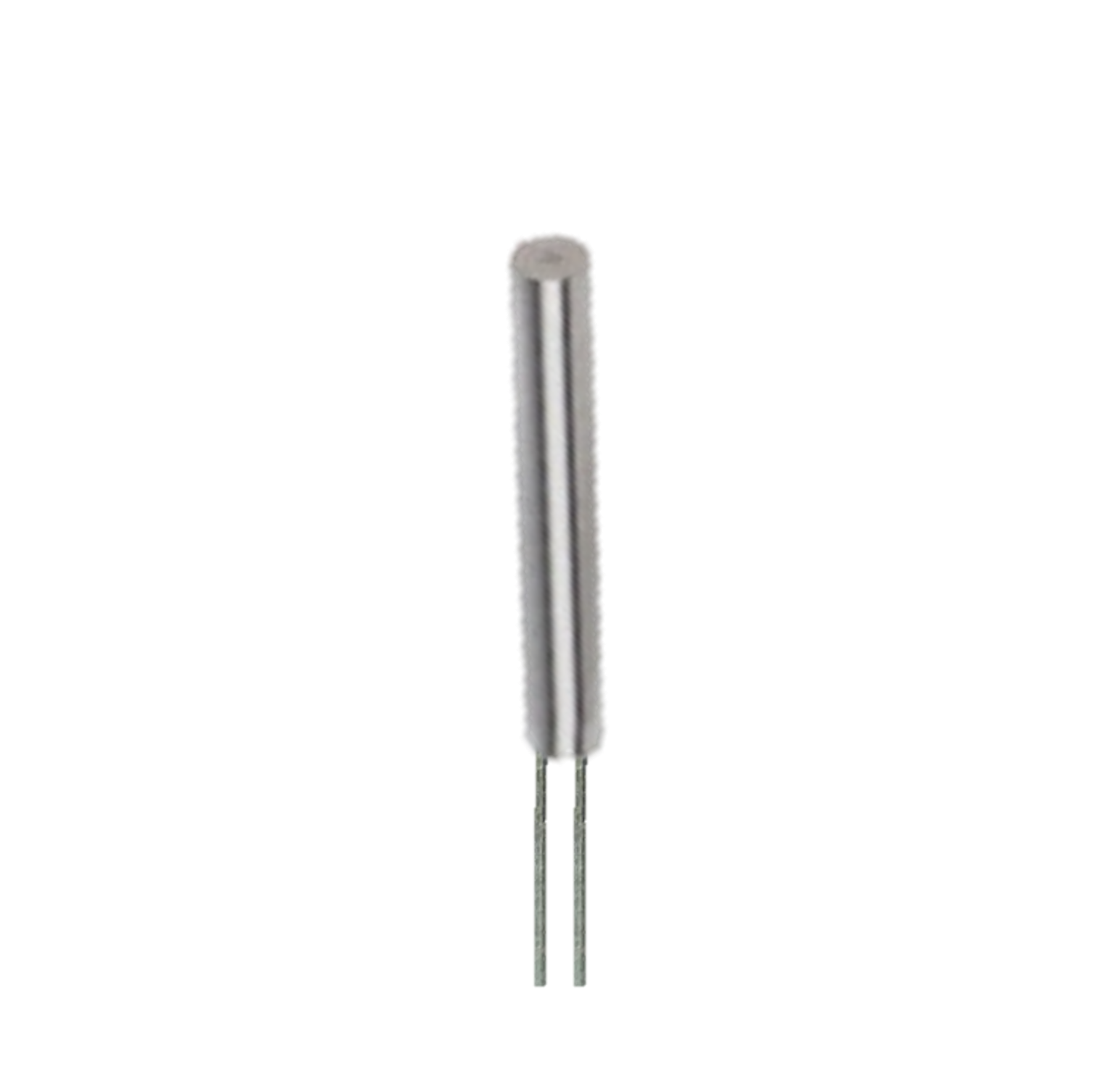
The RTD PT100 is a Resistance Temperature Detector that utilizes a platinum element to measure temperature with exceptional accuracy and stability. It is widely used in industrial, scientific, and laboratory applications due to its reliability and precision. The "PT100" designation indicates that the sensor has a resistance of 100 ohms at 0°C, and its resistance increases linearly with temperature. This makes it ideal for applications requiring precise temperature monitoring and control.
Explore Projects Built with RTD PT100
Explore Projects Built with RTD PT100
Common Applications
- Industrial process control and monitoring
- Laboratory temperature measurements
- HVAC systems
- Food and beverage processing
- Medical equipment
- Environmental monitoring systems
Technical Specifications
The RTD PT100 is designed to provide accurate temperature readings over a wide range of conditions. Below are its key technical details:
| Parameter | Value |
|---|---|
| Sensor Type | Platinum Resistance Temperature Detector (RTD) |
| Nominal Resistance | 100 ohms at 0°C |
| Temperature Range | -200°C to +850°C |
| Tolerance Class | Class A or Class B (varies by model) |
| Temperature Coefficient | ~0.00385 Ω/Ω/°C |
| Accuracy (Class A) | ±(0.15°C + 0.002 × |
| Accuracy (Class B) | ±(0.30°C + 0.005 × |
| Material | Platinum |
| Response Time | Typically 0.5 to 5 seconds |
| Wiring Configuration | 2-wire, 3-wire, or 4-wire |
Pin Configuration and Descriptions
The RTD PT100 does not have traditional "pins" like an integrated circuit but instead uses wires for connection. The wiring configuration depends on the application and the desired accuracy.
| Wiring Type | Description |
|---|---|
| 2-Wire | Simplest configuration; resistance of the lead wires affects measurement accuracy. |
| 3-Wire | Common in industrial applications; compensates for lead wire resistance. |
| 4-Wire | Most accurate; eliminates lead wire resistance from the measurement entirely. |
Usage Instructions
How to Use the RTD PT100 in a Circuit
- Choose the Wiring Configuration: Select 2-wire, 3-wire, or 4-wire based on the required accuracy and the available equipment.
- For high-accuracy applications, use a 4-wire configuration.
- For general-purpose applications, a 3-wire configuration is sufficient.
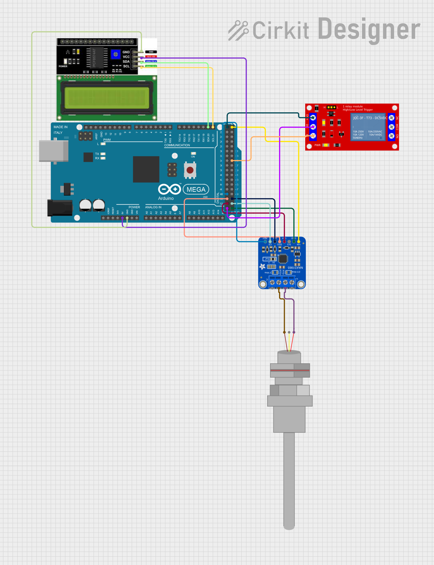
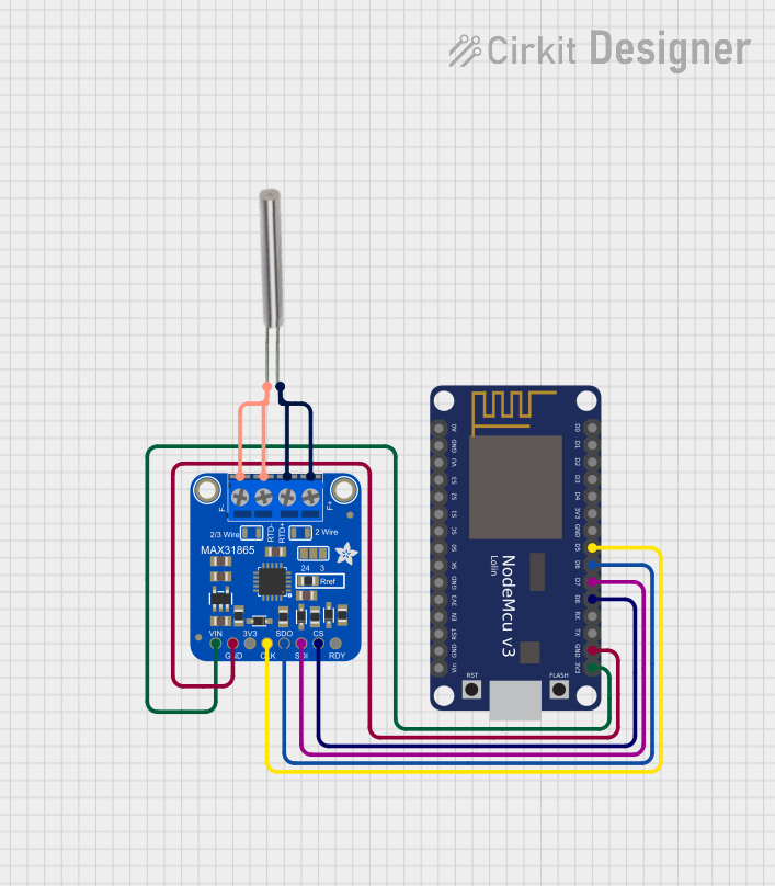
- Connect to a Signal Conditioning Circuit: The RTD PT100 requires a current source and a circuit to measure the voltage drop across the sensor. Use an RTD amplifier or a Wheatstone bridge circuit for this purpose.
- Interface with a Microcontroller: If using a microcontroller like an Arduino UNO, connect the output of the signal conditioning circuit to an analog input pin.
- Calibrate the System: Perform calibration to ensure accurate temperature readings. Use known temperature points (e.g., ice water for 0°C) to verify the sensor's output.
Important Considerations and Best Practices
- Avoid Self-Heating: Use a low current (typically 1 mA or less) to minimize self-heating of the RTD, which can affect accuracy.
- Use Shielded Cables: To reduce noise and interference, use shielded cables for long-distance connections.
- Temperature Compensation: Account for the resistance of lead wires in 2-wire configurations or use 3-wire/4-wire setups to eliminate this issue.
- Protect the Sensor: If used in harsh environments, ensure the RTD is housed in a protective sheath or probe.
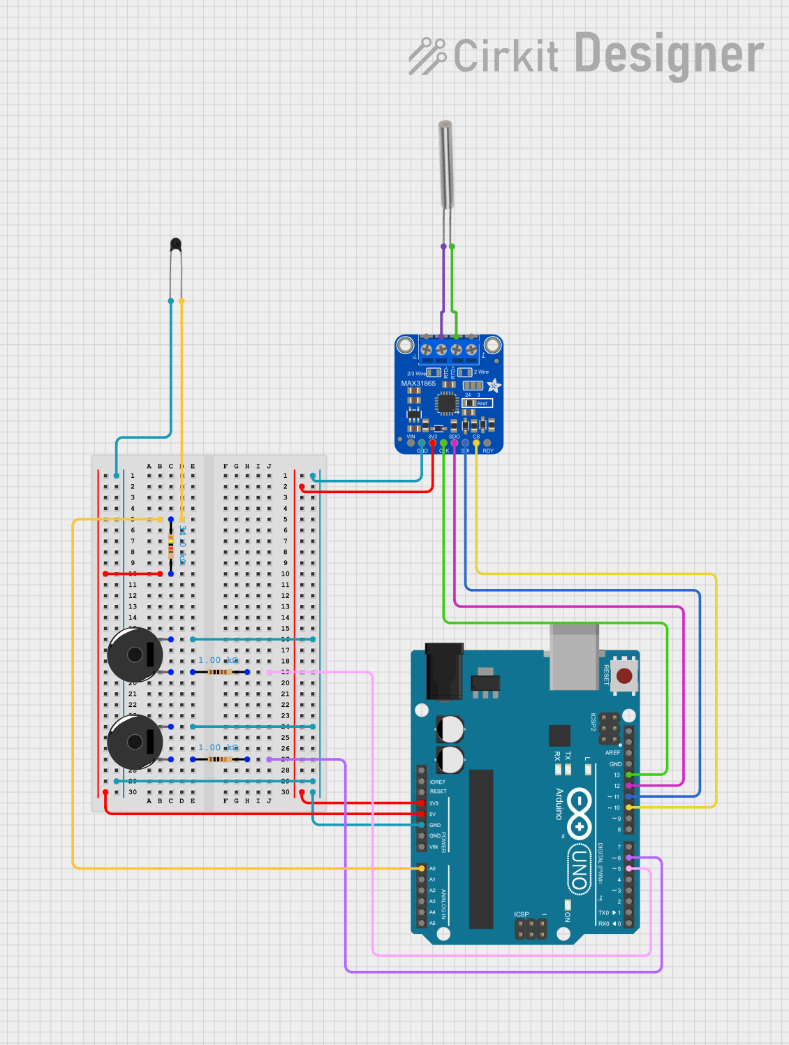
Example: Connecting RTD PT100 to Arduino UNO
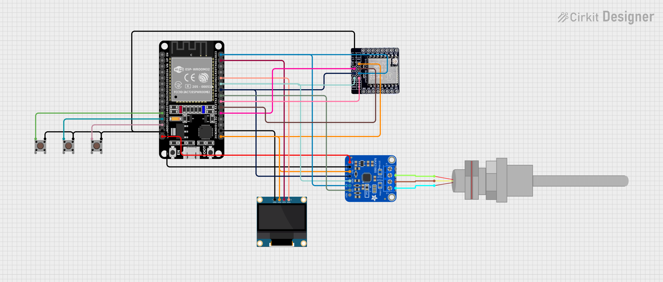
Below is an example of interfacing the RTD PT100 with an Arduino UNO using an RTD amplifier (e.g., MAX31865):
#include <Adafruit_MAX31865.h>

// Define the pins for the MAX31865 RTD amplifier
#define CS_PIN 10  // Chip Select pin
#define DI_PIN 11  // Data In (MOSI)
#define DO_PIN 12  // Data Out (MISO)
#define CLK_PIN 13 // Clock pin

// Create an instance of the MAX31865 class
Adafruit_MAX31865 rtd = Adafruit_MAX31865(CS_PIN, DI_PIN, DO_PIN, CLK_PIN);

void setup() {
  Serial.begin(9600);
  Serial.println("RTD PT100 Temperature Measurement");

  // Initialize the MAX31865 amplifier
  if (!rtd.begin(MAX31865_3WIRE)) {
    // If initialization fails, print an error message
    Serial.println("Failed to initialize MAX31865. Check connections.");
    while (1);
  }
}

void loop() {
  // Read the RTD resistance
  float resistance = rtd.readRTD();

  // Calculate the temperature in Celsius
  float temperature = rtd.temperature(100, 430); // 100 ohms at 0°C, 430 ohms reference resistor

  // Print the results to the Serial Monitor
  Serial.print("Resistance: ");
  Serial.print(resistance);
  Serial.println(" ohms");

  Serial.print("Temperature: ");
  Serial.print(temperature);
  Serial.println(" °C");

  delay(1000); // Wait 1 second before the next reading
}
Troubleshooting and FAQs
Common Issues
Inaccurate Temperature Readings
- Cause: Lead wire resistance in 2-wire configurations.
- Solution: Use a 3-wire or 4-wire configuration to compensate for or eliminate lead wire resistance.
No Output or Erratic Readings
- Cause: Poor connections or incorrect wiring.
- Solution: Verify all connections and ensure the RTD is properly connected to the signal conditioning circuit.
Self-Heating Effects
- Cause: Excessive current through the RTD.
- Solution: Use a low current source (e.g., 1 mA) to minimize self-heating.
Interference or Noise
- Cause: Long cables or unshielded wires.
- Solution: Use shielded cables and keep the RTD wiring away from high-frequency noise sources.
FAQs
Q: Can I use the RTD PT100 without an amplifier?
A: While it is possible, it is not recommended. The RTD PT100 produces a small voltage drop that requires amplification for accurate measurement.
Q: What is the difference between Class A and Class B RTDs?
A: Class A RTDs have higher accuracy than Class B RTDs. Choose Class A for precision applications and Class B for general-purpose use.
Q: Can I use the RTD PT100 in extreme environments?
A: Yes, the RTD PT100 can operate in temperatures ranging from -200°C to +850°C, but ensure it is housed in a protective sheath for harsh conditions.