How to Use SPI OLED Display SSD1306 : Examples, Pinouts, and Specs
Introduction
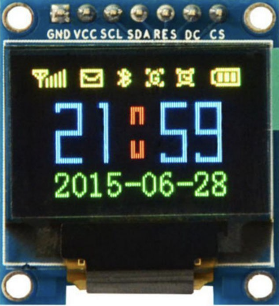
The SPI OLED Display SSD1306 is a compact, low-power OLED display module manufactured by STMicroelectronics (Part ID: OLED Display). It features the SSD1306 driver, which enables high-contrast visuals and wide viewing angles. This display is commonly used in embedded systems due to its efficient power consumption and versatile interfacing capabilities via the Serial Peripheral Interface (SPI).
Explore Projects Built with SPI OLED Display SSD1306


Explore Projects Built with SPI OLED Display SSD1306
Common Applications and Use Cases
- Wearable devices
- IoT dashboards and indicators
- Portable electronics
- Industrial control panels
- Hobbyist and educational projects
Technical Specifications
Below are the key technical details and pin configuration for the SPI OLED Display SSD1306:
Key Technical Details
| Parameter | Value |
|---|---|
| Display Type | OLED |
| Driver IC | SSD1306 |
| Interface | SPI |
| Resolution | 128 x 64 pixels |
| Operating Voltage | 3.3V to 5V |
| Operating Current | ~20mA (typical) |
| Viewing Angle | >160° |
| Display Color | Monochrome (White or Blue) |
| Dimensions | ~27mm x 27mm x 4mm |
| Operating Temperature | -40°C to +85°C |
Pin Configuration and Descriptions
The SPI OLED Display SSD1306 typically has a 7-pin interface. Below is the pinout:
| Pin No. | Pin Name | Description |
|---|---|---|
| 1 | GND | Ground connection |
| 2 | VCC | Power supply (3.3V or 5V) |
| 3 | D0 (SCK) | SPI Clock signal |
| 4 | D1 (MOSI) | SPI Data signal (Master Out Slave In) |
| 5 | RES | Reset pin (active low) |
| 6 | DC | Data/Command control pin (High = Data, Low = Command) |
| 7 | CS | Chip Select (active low, used to enable communication with the display) |
Usage Instructions
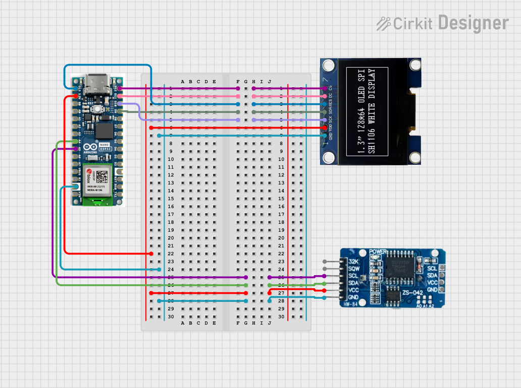
How to Use the Component in a Circuit
- Power Supply: Connect the
VCCpin to a 3.3V or 5V power source and theGNDpin to ground. - SPI Connections:
- Connect the
D0 (SCK)pin to the SPI clock pin of your microcontroller. - Connect the
D1 (MOSI)pin to the SPI data pin of your microcontroller.
- Connect the
- Control Pins:
- Connect the
RESpin to a GPIO pin on your microcontroller for resetting the display. - Connect the
DCpin to a GPIO pin to toggle between data and command modes. - Connect the
CSpin to a GPIO pin to enable/disable communication with the display.
- Connect the
- Pull-Up Resistors: Ensure proper pull-up resistors are used if required by your microcontroller.
Important Considerations and Best Practices
- Voltage Compatibility: Ensure the display's operating voltage matches your microcontroller's logic level (use level shifters if necessary).
- Reset Timing: Hold the
RESpin low for at least 3ms during initialization to reset the display. - SPI Speed: Use an SPI clock frequency of up to 10MHz for optimal performance.
- Library Support: Use libraries like Adafruit SSD1306 or U8g2 for easier integration with platforms like Arduino.
Example Code for Arduino UNO
Below is an example of how to interface the SPI OLED Display SSD1306 with an Arduino UNO using the Adafruit SSD1306 library:
#include <Adafruit_GFX.h>      // Graphics library for OLED
#include <Adafruit_SSD1306.h> // SSD1306 driver library

#define SCREEN_WIDTH 128       // OLED display width in pixels
#define SCREEN_HEIGHT 64       // OLED display height in pixels

// Declaration for SPI OLED display
#define OLED_RESET    4        // Reset pin connected to GPIO 4
#define OLED_DC       5        // Data/Command pin connected to GPIO 5
#define OLED_CS       10       // Chip Select pin connected to GPIO 10
Adafruit_SSD1306 display(SCREEN_WIDTH, SCREEN_HEIGHT, &SPI, OLED_DC, OLED_RESET, OLED_CS);

void setup() {
  // Initialize serial communication for debugging
  Serial.begin(9600);

  // Initialize the OLED display
  if (!display.begin(SSD1306_SWITCHCAPVCC, 0x3C)) { // 0x3C is the I2C address
    Serial.println(F("SSD1306 allocation failed"));
    for (;;); // Halt execution if initialization fails
  }

  // Clear the display buffer
  display.clearDisplay();

  // Display a test message
  display.setTextSize(1);      // Set text size to 1
  display.setTextColor(SSD1306_WHITE); // Set text color to white
  display.setCursor(0, 0);     // Set cursor to top-left corner
  display.println(F("Hello, OLED!")); // Print message
  display.display();           // Update the display with the buffer
}

void loop() {
  // Add your main code here
}
Troubleshooting and FAQs
Common Issues and Solutions
Display Not Turning On:
- Verify the power supply connections (
VCCandGND). - Ensure the
RESpin is properly toggled during initialization.
- Verify the power supply connections (
No Output on Display:
- Check SPI connections (
D0,D1,CS,DC). - Ensure the correct SPI clock frequency is configured in your code.
- Verify that the Adafruit SSD1306 library is installed and properly configured.
- Check SPI connections (
Flickering or Artifacts:
- Reduce the SPI clock speed to avoid signal integrity issues.
- Check for loose or poor-quality connections.
Library Initialization Fails:
- Ensure the correct I2C address (
0x3Cor0x3D) is used in the code. - Confirm that the display is configured for SPI mode (not I2C).
- Ensure the correct I2C address (
FAQs
Q: Can I use this display with a 3.3V microcontroller?
A: Yes, the display is compatible with both 3.3V and 5V logic levels.
Q: What is the maximum SPI clock speed supported?
A: The SSD1306 driver supports SPI clock speeds of up to 10MHz.
Q: Can I use this display in outdoor environments?
A: The display operates within a temperature range of -40°C to +85°C, but it is not waterproof. Use a protective enclosure for outdoor applications.
Q: Is it possible to daisy-chain multiple displays?
A: No, the SSD1306 does not support daisy-chaining. Each display requires a separate SPI connection.
This concludes the documentation for the SPI OLED Display SSD1306.