How to Use GPS: Examples, Pinouts, and Specs
Introduction
The Global Positioning System (GPS) is a satellite-based navigation system that provides accurate location and time information anywhere on Earth. It operates through a network of satellites that transmit signals to GPS receivers, enabling precise positioning and navigation. GPS is widely used in various applications, including automotive navigation, aviation, marine navigation, geolocation services, and outdoor activities like hiking and geocaching.
Explore Projects Built with GPS


Explore Projects Built with GPS
Common Applications:
- Automotive navigation systems
- Smartphones and wearable devices
- Aviation and marine navigation
- Surveying and mapping
- IoT devices for location tracking
- Outdoor recreational activities
Technical Specifications
Below are the key technical details for a typical GPS module:
| Parameter | Specification |
|---|---|
| Manufacturer | GPS |
| Part ID | GPS |
| Operating Voltage | 3.3V to 5V |
| Operating Current | 20mA to 50mA |
| Communication Protocol | UART (TX, RX) or I2C |
| Baud Rate | 9600 bps (default, configurable) |
| Position Accuracy | ±2.5 meters (typical) |
| Time to First Fix (TTFF) | Cold Start: ~30 seconds, Hot Start: ~1 second |
| Operating Temperature | -40°C to +85°C |
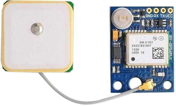
| Antenna Type | External or built-in patch antenna |
Pin Configuration
The GPS module typically has the following pinout:
| Pin | Name | Description |
|---|---|---|
| 1 | VCC | Power supply input (3.3V to 5V) |
| 2 | GND | Ground |
| 3 | TX | Transmit data (UART output) |
| 4 | RX | Receive data (UART input) |
| 5 | PPS | Pulse per second (timing signal output) |
| 6 | EN | Enable pin (optional, for power control) |
Usage Instructions
How to Use the GPS Module in a Circuit
- Power Supply: Connect the
VCCpin to a 3.3V or 5V power source and theGNDpin to ground. - Data Communication: Use the
TXandRXpins to establish UART communication with a microcontroller or computer. Ensure the baud rate matches the GPS module's default (typically 9600 bps). - Antenna: If the module requires an external antenna, connect it to the designated antenna port for optimal signal reception.
- Enable Pin: If the module includes an
ENpin, it can be used to enable or disable the module for power-saving purposes.
Important Considerations:
- Signal Reception: Ensure the GPS module has a clear view of the sky for optimal satellite signal reception. Avoid using it indoors or in areas with heavy obstructions.
- Baud Rate Configuration: If needed, configure the baud rate using AT commands or the manufacturer's software tools.
- Power Supply: Use a stable power source to avoid performance issues or resets.
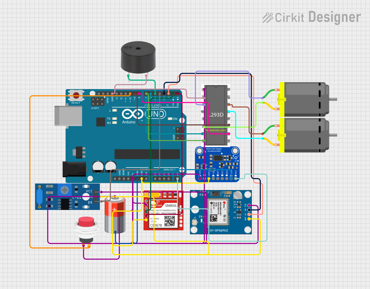
Example: Connecting GPS to Arduino UNO
Below is an example of how to connect and use a GPS module with an Arduino UNO:
Circuit Connections:
VCC→ 5V on ArduinoGND→ GND on ArduinoTX→ Pin 4 on ArduinoRX→ Pin 3 on Arduino
Arduino Code:
#include <SoftwareSerial.h>

// Create a SoftwareSerial object for GPS communication
SoftwareSerial gpsSerial(3, 4); // RX, TX

void setup() {
  Serial.begin(9600); // Initialize Serial Monitor at 9600 bps
  gpsSerial.begin(9600); // Initialize GPS module at 9600 bps
  Serial.println("GPS Module Initialized");
}

void loop() {
  // Check if data is available from the GPS module
  while (gpsSerial.available()) {
    char c = gpsSerial.read(); // Read one character from GPS
    Serial.print(c); // Print the character to Serial Monitor
  }
}
Notes:
- Use the Arduino Serial Monitor to view the GPS data output.
- The GPS module will output NMEA sentences, which can be parsed for location, time, and other data.
Troubleshooting and FAQs
Common Issues and Solutions:
No GPS Fix (No Location Data):
- Cause: Poor satellite signal reception.
- Solution: Move the GPS module to an open area with a clear view of the sky.
Garbage Data on Serial Monitor:
- Cause: Incorrect baud rate configuration.
- Solution: Ensure the baud rate in the code matches the GPS module's default (e.g., 9600 bps).
Module Not Powering On:
- Cause: Insufficient or unstable power supply.
- Solution: Verify the power source and connections to the
VCCandGNDpins.
Intermittent Data Output:
- Cause: Electrical noise or interference.
- Solution: Use proper decoupling capacitors and shield the module from interference.
FAQs:
Q: Can the GPS module work indoors?
- A: GPS modules typically require a clear view of the sky for accurate positioning. Indoors, the signal may be weak or unavailable.
Q: How do I parse NMEA sentences?
- A: Use libraries like TinyGPS++ or Adafruit GPS to parse NMEA sentences and extract useful data like latitude, longitude, and time.
Q: What is the purpose of the PPS pin?
- A: The PPS (Pulse Per Second) pin provides a precise timing signal that can be used for synchronization in time-sensitive applications.
Q: Can I use the GPS module with a 3.3V microcontroller?
- A: Yes, most GPS modules support 3.3V operation. Check the module's datasheet to confirm compatibility.
By following this documentation, users can effectively integrate and troubleshoot a GPS module in their projects.