How to Use RPLIDAR A1M8: Examples, Pinouts, and Specs
Introduction
The RPLIDAR A1M8, manufactured by Slamtec, is a 360-degree laser scanner designed for high-resolution distance measurements. It is widely used in applications such as robotics, autonomous vehicles, and other systems requiring precise mapping and navigation. The device enables the creation of detailed 2D and 3D maps of the surrounding environment, making it an essential tool for SLAM (Simultaneous Localization and Mapping) tasks.
Explore Projects Built with RPLIDAR A1M8

Explore Projects Built with RPLIDAR A1M8
Common Applications
- Autonomous robots for navigation and obstacle avoidance
- Indoor and outdoor mapping
- Drone-based surveying
- Smart home devices for spatial awareness
- Research and development in robotics and AI
Technical Specifications
The following table outlines the key technical details of the RPLIDAR A1M8:
| Specification | Details |
|---|---|
| Measurement Range | 0.15 m to 12 m (indoor environment) |
| Scanning Frequency | 5 Hz to 10 Hz (adjustable) |
| Angular Resolution | 1° to 1.5° |
| Distance Resolution | < 1% of the distance |
| Laser Wavelength | 785 nm (infrared) |
| Laser Safety Class | Class 1 (eye-safe) |
| Communication Interface | UART (3.3V TTL) |
| Input Voltage | 5 V DC |
| Power Consumption | 2 W (typical) |
| Operating Temperature | 0°C to 40°C |
| Dimensions | 70 mm (diameter) x 41 mm (height) |
| Weight | 190 g |
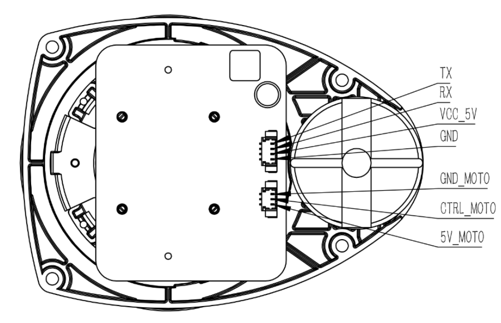
Pin Configuration
The RPLIDAR A1M8 uses a 5-pin interface for communication and power. The pin configuration is as follows:
| Pin Number | Pin Name | Description |
|---|---|---|
| 1 | VCC | Power input (5 V DC) |
| 2 | GND | Ground |
| 3 | TX | UART Transmit (3.3V TTL) |
| 4 | RX | UART Receive (3.3V TTL) |
| 5 | MOTOCTL | Motor control signal (PWM input) |
Usage Instructions
Connecting the RPLIDAR A1M8
- Power Supply: Connect the VCC and GND pins to a stable 5V DC power source.
- Communication: Use the TX and RX pins to establish a UART connection with a microcontroller or computer. Ensure the UART voltage level is 3.3V TTL.
- Motor Control: Use the MOTOCTL pin to control the motor speed. A PWM signal can be applied to adjust the scanning frequency.
Using with Arduino UNO
To use the RPLIDAR A1M8 with an Arduino UNO, you will need a 3.3V to 5V level shifter for the UART pins. Below is an example Arduino sketch to interface with the RPLIDAR:
#include <RPLidar.h> // Include the RPLIDAR library

// Define the RPLIDAR serial connection
#define RPLIDAR_RX 10 // RX pin connected to TX of RPLIDAR (via level shifter)
#define RPLIDAR_TX 11 // TX pin connected to RX of RPLIDAR (via level shifter)
RPLidar lidar;

// Setup function
void setup() {
  Serial.begin(115200); // Initialize serial monitor
  lidar.begin(Serial1); // Initialize RPLIDAR on Serial1 (pins 10 and 11)

  // Check if the RPLIDAR is connected
  if (lidar.checkHealth()) {
    Serial.println("RPLIDAR is healthy and ready.");
  } else {
    Serial.println("RPLIDAR health check failed!");
    while (1); // Halt execution if health check fails
  }
}

// Main loop
void loop() {
  if (IS_OK(lidar.waitPoint())) {
    // Get the distance and angle of the current scan point
    float distance = lidar.getCurrentPoint().distance; // Distance in mm
    float angle = lidar.getCurrentPoint().angle;       // Angle in degrees

    // Print the data to the serial monitor
    Serial.print("Distance: ");
    Serial.print(distance);
    Serial.print(" mm, Angle: ");
    Serial.print(angle);
    Serial.println(" degrees");
  } else {
    Serial.println("Failed to get scan data.");
  }
}
Best Practices
- Ensure the RPLIDAR is mounted on a stable surface to minimize vibrations during operation.
- Avoid exposing the device to direct sunlight or reflective surfaces, as these can interfere with laser measurements.
- Use a proper level shifter when interfacing with 5V logic devices like Arduino UNO.
- Regularly clean the lens to maintain measurement accuracy.
Troubleshooting and FAQs
Common Issues
No Data Output
- Cause: Incorrect wiring or UART configuration.
- Solution: Verify the connections and ensure the UART baud rate matches the RPLIDAR's default (115200 bps).
Motor Not Spinning
- Cause: MOTOCTL pin not receiving a valid PWM signal.
- Solution: Check the PWM signal and ensure it is within the required frequency range.
Inaccurate Measurements
- Cause: Dirty lens or environmental interference.
- Solution: Clean the lens and avoid reflective or overly bright environments.
Health Check Fails
- Cause: Hardware malfunction or improper power supply.
- Solution: Ensure a stable 5V power supply and check for physical damage.
FAQs
Q: Can the RPLIDAR A1M8 be used outdoors?
A: Yes, but it performs best in controlled environments. Direct sunlight or rain can affect its performance.
Q: What is the maximum scanning frequency?
A: The RPLIDAR A1M8 supports up to 10 Hz scanning frequency.
Q: Is the laser safe for human eyes?
A: Yes, the RPLIDAR A1M8 uses a Class 1 laser, which is eye-safe under normal operating conditions.
Q: Can it create 3D maps?
A: The RPLIDAR A1M8 is primarily designed for 2D mapping. However, it can be used in conjunction with other sensors to create 3D maps.
Q: How do I update the firmware?
A: Firmware updates can be performed using Slamtec's official tools and software. Refer to the manufacturer's website for detailed instructions.