How to Use boost converter 3.7V-5V: Examples, Pinouts, and Specs
Introduction
A boost converter is a DC-DC converter that steps up voltage from a lower level (3.7V) to a higher level (5V). This component is essential for powering devices that require a higher voltage from a lower voltage source, such as lithium-ion batteries. The 3.7V-5V boost converter is compact, efficient, and widely used in portable electronics, battery-powered devices, and embedded systems.
Explore Projects Built with boost converter 3.7V-5V


Explore Projects Built with boost converter 3.7V-5V
Common Applications and Use Cases
- Powering 5V microcontrollers (e.g., Arduino, Raspberry Pi) from a 3.7V lithium-ion battery.
- Charging USB devices from a single-cell battery.
- Portable power banks and battery packs.
- LED lighting systems requiring a stable 5V supply.
- Wireless communication modules and IoT devices.
Technical Specifications
The following table outlines the key technical details of the 3.7V-5V boost converter:
| Parameter | Value |
|---|---|
| Input Voltage Range | 2.5V - 4.5V |
| Output Voltage | 5V ± 0.1V |
| Maximum Output Current | 1A (depending on input voltage) |
| Efficiency | Up to 90% |
| Switching Frequency | 1.2 MHz |
| Operating Temperature | -40°C to +85°C |
| Dimensions | Typically 22mm x 17mm x 4mm |
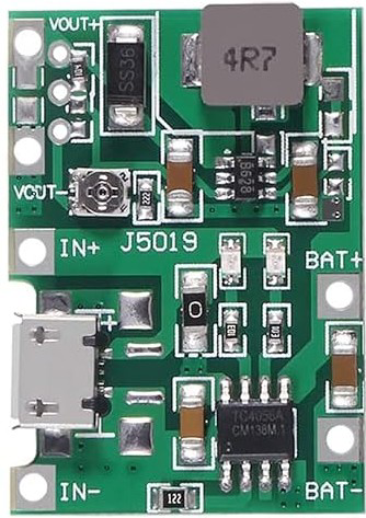
Pin Configuration and Descriptions
The boost converter typically has the following pin configuration:
| Pin Name | Description |
|---|---|
| VIN | Input voltage pin. Connect to the positive terminal of the 3.7V power source. |
| GND | Ground pin. Connect to the negative terminal of the power source. |
| VOUT | Output voltage pin. Provides the boosted 5V output. |
| EN (optional) | Enable pin. Used to turn the converter on/off (active high). |
Usage Instructions
How to Use the Component in a Circuit
Connect the Input Voltage:
- Connect the VIN pin to the positive terminal of a 3.7V power source (e.g., a lithium-ion battery).
- Connect the GND pin to the negative terminal of the power source.
Connect the Output Voltage:
- Connect the VOUT pin to the load that requires a 5V power supply.
- Ensure the load does not exceed the maximum output current of the boost converter.
Optional Enable Pin:
- If the boost converter has an EN (enable) pin, connect it to a logic HIGH signal (e.g., 3.3V or 5V) to activate the converter. Leave it unconnected or pull it LOW to disable the converter.
Add Decoupling Capacitors:
- Place a capacitor (e.g., 10µF) between VIN and GND to stabilize the input voltage.
- Place another capacitor (e.g., 22µF) between VOUT and GND to smooth the output voltage.
Important Considerations and Best Practices
- Input Voltage Range: Ensure the input voltage stays within the specified range (2.5V - 4.5V). Exceeding this range may damage the converter.
- Load Current: Do not exceed the maximum output current (1A). Overloading the converter can cause overheating or failure.
- Heat Dissipation: If the converter operates near its maximum current, ensure proper ventilation or add a heatsink to prevent overheating.
- Wiring: Use short, thick wires for connections to minimize voltage drops and interference.
- Polarity: Double-check the polarity of the input and output connections to avoid damage.
Example: Using the Boost Converter with an Arduino UNO
The following example demonstrates how to power an Arduino UNO using a 3.7V-5V boost converter and a lithium-ion battery.
Circuit Connections
- Connect the VIN pin of the boost converter to the positive terminal of the 3.7V lithium-ion battery.
- Connect the GND pin of the boost converter to the negative terminal of the battery.
- Connect the VOUT pin of the boost converter to the 5V pin of the Arduino UNO.
- Connect the GND pin of the boost converter to the GND pin of the Arduino UNO.
Sample Code
The following Arduino code blinks an LED connected to pin 13. The boost converter provides the 5V power supply to the Arduino UNO.
// Blink an LED connected to pin 13
void setup() {
  pinMode(13, OUTPUT); // Set pin 13 as an output
}

void loop() {
  digitalWrite(13, HIGH); // Turn the LED on
  delay(1000);            // Wait for 1 second
  digitalWrite(13, LOW);  // Turn the LED off
  delay(1000);            // Wait for 1 second
}
Troubleshooting and FAQs
Common Issues and Solutions
No Output Voltage:
- Cause: Incorrect wiring or loose connections.
- Solution: Double-check all connections, ensuring proper polarity and secure wiring.
Output Voltage is Unstable:
- Cause: Insufficient decoupling capacitors or excessive load.
- Solution: Add capacitors (e.g., 10µF and 22µF) to stabilize the input and output. Reduce the load if it exceeds the maximum current.
Converter Overheats:
- Cause: Operating near or beyond the maximum current rating.
- Solution: Reduce the load or improve heat dissipation with a heatsink or better ventilation.
Low Efficiency:
- Cause: Input voltage is too low or load is too high.
- Solution: Ensure the input voltage is within the specified range and reduce the load.
FAQs
Q: Can I use this boost converter with a 3.3V input?
A: Yes, as long as the input voltage is within the range of 2.5V to 4.5V, the converter will step it up to 5V.
Q: What happens if I connect the input voltage in reverse?
A: Reversing the input voltage can damage the boost converter. Always double-check the polarity before powering the circuit.
Q: Can I use this boost converter to charge a 5V USB device?
A: Yes, but ensure the device's current requirements do not exceed the maximum output current of the converter (1A).
Q: Is it safe to use this converter with a lithium-ion battery?
A: Yes, the converter is designed for such applications. However, ensure the battery has proper protection circuitry to prevent over-discharge or overcurrent.
This concludes the documentation for the 3.7V-5V boost converter.