How to Use ESP-32 DEVKIT-V1 Expansion Board: Examples, Pinouts, and Specs
Introduction
The ESP-32 DEVKIT-V1 Expansion Board, manufactured by Espressif, is a versatile development board designed for IoT (Internet of Things) applications. It features the powerful ESP32 chip, which integrates Wi-Fi and Bluetooth capabilities, making it suitable for a wide range of wireless communication projects. This board is ideal for prototyping, smart home devices, wearable electronics, and other connected applications.
Explore Projects Built with ESP-32 DEVKIT-V1 Expansion Board


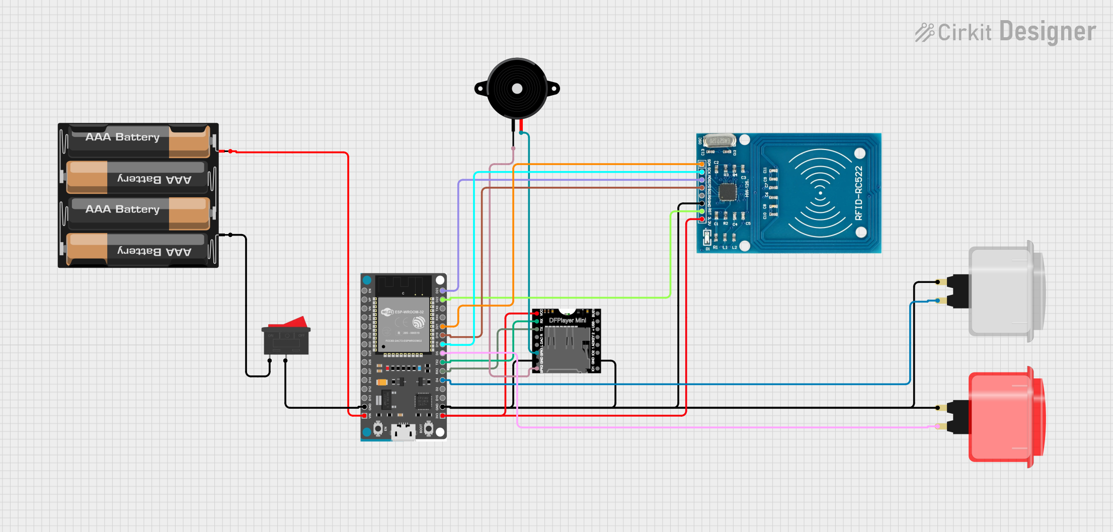
Explore Projects Built with ESP-32 DEVKIT-V1 Expansion Board
Common Applications and Use Cases
- IoT devices and smart home automation
- Wireless sensor networks
- Wearable technology
- Robotics and remote control systems
- Data logging and monitoring systems
- Bluetooth-enabled applications
Technical Specifications
The ESP-32 DEVKIT-V1 Expansion Board is built around the ESP32 microcontroller, which offers high performance and low power consumption. Below are the key technical details:
Key Technical Details
| Parameter | Specification |
|---|---|
| Microcontroller | ESP32 Dual-Core Tensilica LX6 |
| Clock Speed | Up to 240 MHz |
| Flash Memory | 4 MB (varies by model) |
| SRAM | 520 KB |
| Wi-Fi Standard | 802.11 b/g/n |
| Bluetooth Standard | Bluetooth 4.2 (Classic and BLE) |
| Operating Voltage | 3.3V |
| Input Voltage (VIN) | 5V (via USB or VIN pin) |
| GPIO Pins | 30 (varies by board version) |
| ADC Channels | 18 |
| DAC Channels | 2 |
| Communication Interfaces | UART, SPI, I2C, I2S, PWM |
| Power Consumption | Ultra-low power (varies by mode) |
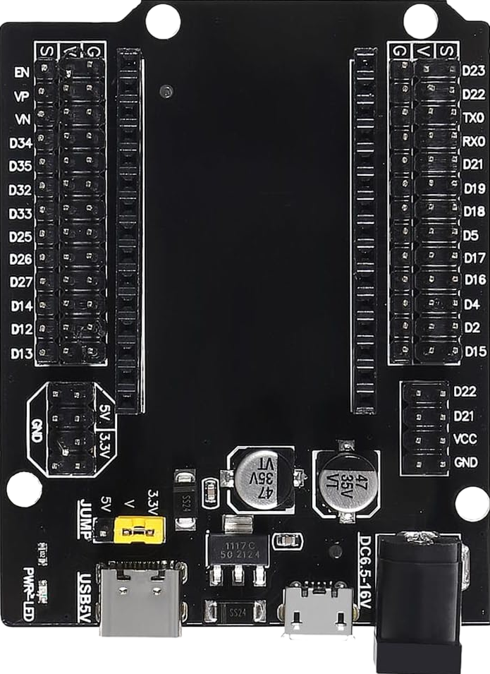
Pin Configuration and Descriptions
The ESP-32 DEVKIT-V1 Expansion Board has a 30-pin layout. Below is the pin configuration:
| Pin Number | Pin Name | Description |
|---|---|---|
| 1 | EN | Enable pin (active high) |
| 2 | IO23 | GPIO23, SPI MOSI |
| 3 | IO22 | GPIO22, I2C SCL |
| 4 | IO21 | GPIO21, I2C SDA |
| 5 | GND | Ground |
| 6 | VIN | Input voltage (5V) |
| 7 | IO19 | GPIO19, SPI MISO |
| 8 | IO18 | GPIO18, SPI SCK |
| 9 | IO17 | GPIO17, UART2 TX |
| 10 | IO16 | GPIO16, UART2 RX |
| ... | ... | ... (remaining pins follow similar format) |
Refer to the official datasheet for a complete pinout diagram.
Usage Instructions
How to Use the ESP-32 DEVKIT-V1 in a Circuit
Powering the Board:
- Connect the board to a computer or power source using a micro-USB cable.
- Alternatively, supply 5V to the VIN pin and connect GND to the ground.
Programming the Board:
- Install the Arduino IDE and add the ESP32 board support package.
- Select "ESP32 Dev Module" from the Tools > Board menu.
- Connect the board to your computer and select the appropriate COM port.
Connecting Peripherals:
- Use the GPIO pins to connect sensors, actuators, or other peripherals.
- Ensure that the voltage levels of connected devices are compatible with the 3.3V logic of the ESP32.
Uploading Code:
- Write your code in the Arduino IDE or another supported environment.
- Click the "Upload" button to flash the code to the ESP32.
Example Code: Blinking an LED
The following example demonstrates how to blink an LED connected to GPIO2:
// Define the GPIO pin where the LED is connected
const int ledPin = 2;

void setup() {
  // Set the LED pin as an output
  pinMode(ledPin, OUTPUT);
}

void loop() {
  // Turn the LED on
  digitalWrite(ledPin, HIGH);
  delay(1000); // Wait for 1 second

  // Turn the LED off
  digitalWrite(ledPin, LOW);
  delay(1000); // Wait for 1 second
}
Important Considerations and Best Practices
- Voltage Levels: Ensure that all connected peripherals operate at 3.3V logic levels. Use level shifters if necessary.
- Power Supply: Use a stable power source to avoid unexpected resets or malfunctions.
- GPIO Usage: Some GPIO pins have specific functions during boot (e.g., GPIO0, GPIO2). Avoid using these pins for critical peripherals.
- Heat Management: The ESP32 chip may heat up during operation. Ensure proper ventilation if used in enclosed spaces.
Troubleshooting and FAQs
Common Issues and Solutions
Board Not Detected by Computer:
- Ensure the USB cable is functional and supports data transfer.
- Install the correct USB-to-serial driver for your operating system.
Code Upload Fails:
- Check the selected COM port in the Arduino IDE.
- Press and hold the "BOOT" button on the board while uploading the code.
Wi-Fi Connection Issues:
- Verify the SSID and password in your code.
- Ensure the router is within range and supports 2.4 GHz Wi-Fi.
Random Resets or Instability:
- Check the power supply for stability.
- Avoid using GPIO pins with special boot functions for peripherals.
FAQs
Q: Can I power the board with a battery?
A: Yes, you can use a 3.7V LiPo battery connected to the 3.3V pin or a 5V source connected to the VIN pin.
Q: How do I use Bluetooth on the ESP32?
A: The ESP32 supports both Bluetooth Classic and BLE. Use the BluetoothSerial or BLE libraries in the Arduino IDE to implement Bluetooth functionality.
Q: What is the maximum number of GPIO pins I can use?
A: The ESP32 DEVKIT-V1 provides up to 30 GPIO pins, but some are reserved for specific functions. Refer to the pinout diagram for details.
Q: Can I use the ESP32 with MicroPython?
A: Yes, the ESP32 supports MicroPython. Flash the MicroPython firmware to the board and use a compatible IDE like Thonny.
By following this documentation, you can effectively utilize the ESP-32 DEVKIT-V1 Expansion Board for your IoT and embedded system projects.