Cirkit Designer Logo
Cirkit Designer
Your all-in-one circuit design IDE
Home / 
Component Documentation

How to Use RP0505S DCDC Wandler: Examples, Pinouts, and Specs

Image of RP0505S DCDC Wandler
Cirkit Designer LogoDesign with RP0505S DCDC Wandler in Cirkit Designer

Introduction

The RP0505S is a compact and efficient DC-DC converter designed to step down voltage from a higher input level to a stable 5V output. This component is widely used in applications requiring reliable power conversion with minimal energy loss and heat generation. Its small form factor and high efficiency make it ideal for embedded systems, industrial automation, IoT devices, and portable electronics.

Explore Projects Built with RP0505S DCDC Wandler

Use Cirkit Designer to design, explore, and prototype these projects online. Some projects support real-time simulation. Click "Open Project" to start designing instantly!
Multi-Stage Voltage Regulation and Indicator LED Circuit
Image of Subramanyak_Power_Circuit: A project utilizing RP0505S DCDC Wandler in a practical application
This circuit is designed for power management, featuring buck and boost converters for voltage adjustment, and linear regulators for stable voltage output. It includes LEDs for status indication, and terminal blocks for external connections.
Cirkit Designer LogoOpen Project in Cirkit Designer
Battery-Powered UPS System with Waveshare UPS 3S and Solar Charger
Image of Copy of s: A project utilizing RP0505S DCDC Wandler in a practical application
This circuit is a power management system that integrates a 12V power supply, a solar charger power bank, and multiple Li-ion batteries to provide a stable power output. The Waveshare UPS 3S manages the input from the power sources and batteries, ensuring continuous power delivery. The MRB045 module is used to interface the solar charger with the rest of the system.
Cirkit Designer LogoOpen Project in Cirkit Designer
USB-Powered DC Gear Motor with LED Indicator
Image of Hand Crank mobile charger : A project utilizing RP0505S DCDC Wandler in a practical application
This circuit appears to be a power supply unit with a bridge rectifier connected to a DC gear motor, indicating it is designed to convert AC to DC power for the motor. An electrolytic capacitor is used for smoothing the DC output, and a 7805 voltage regulator is included to provide a stable 5V output. Additionally, there is an LED with a series resistor, likely serving as a power indicator light.
Cirkit Designer LogoOpen Project in Cirkit Designer
Battery-Powered UPS with Step-Down Buck Converter and BMS
Image of Mini ups: A project utilizing RP0505S DCDC Wandler in a practical application
This circuit is a power management system that steps down a 240V AC input to a lower DC voltage using a buck converter, which then powers a 40W UPS. The UPS is controlled by a rocker switch and is backed up by a battery management system (BMS) connected to three 3.7V batteries in series, ensuring continuous power supply.
Cirkit Designer LogoOpen Project in Cirkit Designer

Explore Projects Built with RP0505S DCDC Wandler

Use Cirkit Designer to design, explore, and prototype these projects online. Some projects support real-time simulation. Click "Open Project" to start designing instantly!
Image of Subramanyak_Power_Circuit: A project utilizing RP0505S DCDC Wandler in a practical application
Multi-Stage Voltage Regulation and Indicator LED Circuit
This circuit is designed for power management, featuring buck and boost converters for voltage adjustment, and linear regulators for stable voltage output. It includes LEDs for status indication, and terminal blocks for external connections.
Cirkit Designer LogoOpen Project in Cirkit Designer
Image of Copy of s: A project utilizing RP0505S DCDC Wandler in a practical application
Battery-Powered UPS System with Waveshare UPS 3S and Solar Charger
This circuit is a power management system that integrates a 12V power supply, a solar charger power bank, and multiple Li-ion batteries to provide a stable power output. The Waveshare UPS 3S manages the input from the power sources and batteries, ensuring continuous power delivery. The MRB045 module is used to interface the solar charger with the rest of the system.
Cirkit Designer LogoOpen Project in Cirkit Designer
Image of Hand Crank mobile charger : A project utilizing RP0505S DCDC Wandler in a practical application
USB-Powered DC Gear Motor with LED Indicator
This circuit appears to be a power supply unit with a bridge rectifier connected to a DC gear motor, indicating it is designed to convert AC to DC power for the motor. An electrolytic capacitor is used for smoothing the DC output, and a 7805 voltage regulator is included to provide a stable 5V output. Additionally, there is an LED with a series resistor, likely serving as a power indicator light.
Cirkit Designer LogoOpen Project in Cirkit Designer
Image of Mini ups: A project utilizing RP0505S DCDC Wandler in a practical application
Battery-Powered UPS with Step-Down Buck Converter and BMS
This circuit is a power management system that steps down a 240V AC input to a lower DC voltage using a buck converter, which then powers a 40W UPS. The UPS is controlled by a rocker switch and is backed up by a battery management system (BMS) connected to three 3.7V batteries in series, ensuring continuous power supply.
Cirkit Designer LogoOpen Project in Cirkit Designer

Common Applications

  • Powering microcontrollers and sensors in embedded systems
  • Voltage regulation in industrial control systems
  • Battery-powered devices requiring efficient power conversion
  • IoT devices and low-power wireless modules

Technical Specifications

Key Specifications

Parameter Value
Input Voltage Range 4.5V to 9V
Output Voltage 5V (regulated)
Output Current Up to 1A
Efficiency Up to 85%
Operating Temperature -40°C to +85°C
Package Type SIP-4 (Single Inline Package)
Isolation Voltage 1kV DC

Pin Configuration and Descriptions

Pin Number Pin Name Description
1 +Vin Positive input voltage (4.5V to 9V)
2 -Vin Negative input voltage (ground)
3 +Vout Positive regulated output voltage (5V)
4 -Vout Negative regulated output voltage (ground)

Usage Instructions

How to Use the RP0505S in a Circuit

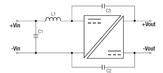
  1. Input Voltage Connection: Connect the input voltage source (4.5V to 9V) to the +Vin and -Vin pins. Ensure the input voltage is within the specified range to avoid damage to the component.
  2. Output Voltage Connection: Connect the load to the +Vout and -Vout pins. The load should not exceed the maximum output current of 1A.
  3. Bypass Capacitors: For stable operation, place a 10µF capacitor across the input pins and a 10µF capacitor across the output pins. These capacitors help filter noise and improve stability.
  4. Thermal Considerations: Ensure adequate ventilation or heat dissipation if the component operates near its maximum current rating.

Important Considerations

  • Input Voltage Range: Do not exceed the maximum input voltage of 9V, as this may damage the converter.
  • Load Regulation: Ensure the load does not exceed 1A to maintain stable output voltage.
  • Isolation: The RP0505S provides 1kV DC isolation, making it suitable for applications requiring electrical isolation between input and output.

Example: Using RP0505S with an Arduino UNO

The RP0505S can be used to power an Arduino UNO from a 6V battery. Below is an example circuit and Arduino code to blink an LED.

Circuit Setup

  1. Connect the 6V battery to the +Vin and -Vin pins of the RP0505S.
  2. Connect the +Vout pin to the Arduino UNO's 5V pin and the -Vout pin to the GND pin.
  3. Connect an LED with a 220Ω resistor to pin 13 of the Arduino UNO.

Arduino Code

// Simple LED Blink Example
// This code blinks an LED connected to pin 13 of the Arduino UNO.

void setup() {
  pinMode(13, OUTPUT); // Set pin 13 as an output pin
}

void loop() {
  digitalWrite(13, HIGH); // Turn the LED on
  delay(1000);            // Wait for 1 second
  digitalWrite(13, LOW);  // Turn the LED off
  delay(1000);            // Wait for 1 second
}

Troubleshooting and FAQs

Common Issues and Solutions

  1. No Output Voltage:

    • Cause: Input voltage is outside the specified range.
    • Solution: Verify that the input voltage is between 4.5V and 9V.
  2. Overheating:

    • Cause: Excessive load current or poor ventilation.
    • Solution: Ensure the load does not exceed 1A and improve airflow around the component.
  3. Output Voltage Instability:

    • Cause: Insufficient bypass capacitors.
    • Solution: Add 10µF capacitors across the input and output pins.
  4. Component Damage:

    • Cause: Input voltage exceeds 9V or reverse polarity connection.
    • Solution: Use a voltage regulator or protection diode to prevent overvoltage or reverse polarity.

FAQs

Q1: Can the RP0505S be used with a 12V input?
A1: No, the maximum input voltage is 9V. Using a 12V input may damage the component.

Q2: Is the RP0505S suitable for powering sensitive analog circuits?
A2: Yes, but ensure proper filtering with capacitors to minimize noise.

Q3: Can I use the RP0505S in a high-temperature environment?
A3: The RP0505S operates reliably within -40°C to +85°C. Ensure adequate cooling if used near the upper temperature limit.