Cirkit Designer
Your all-in-one circuit design IDE
Home /
Component Documentation
How to Use Motor Hat: Examples, Pinouts, and Specs
Introduction
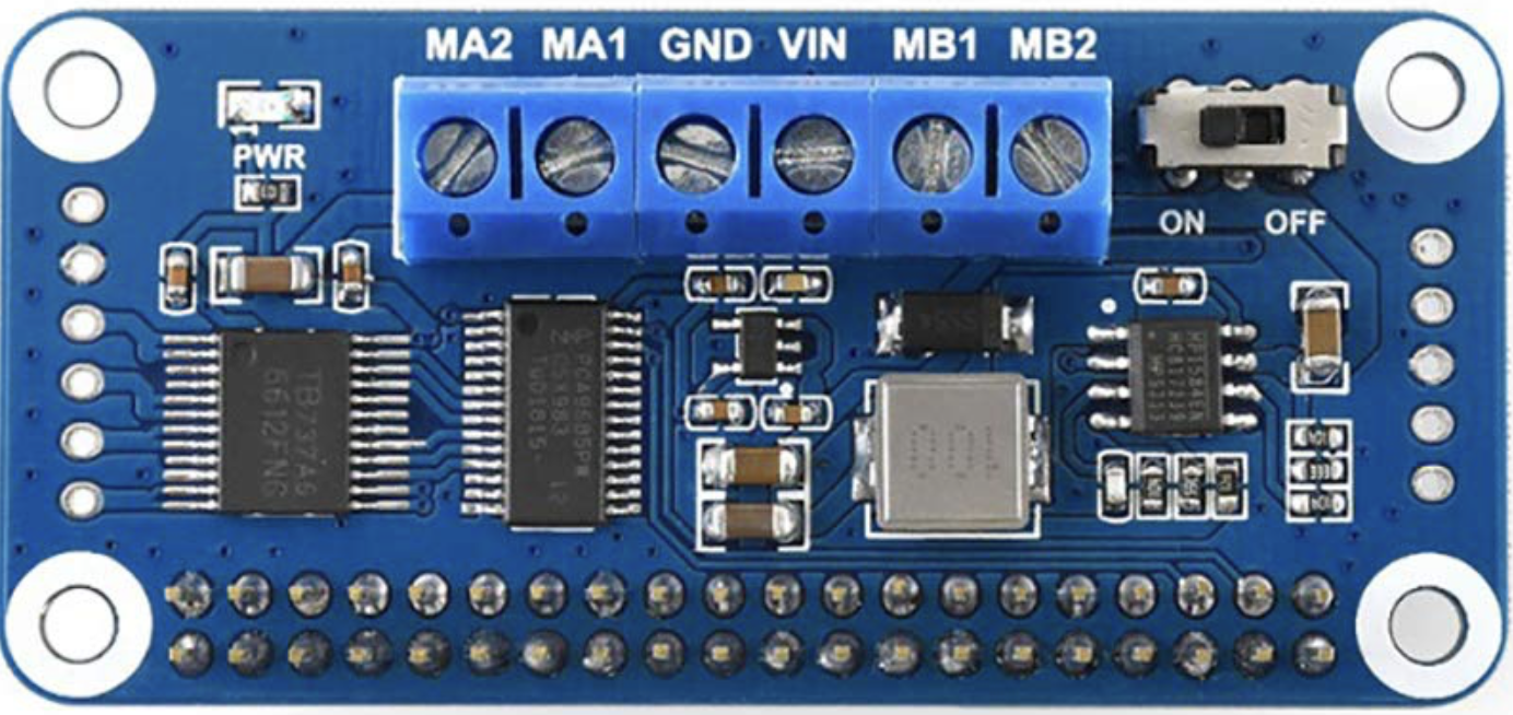
A Motor Hat is an add-on board designed for microcontrollers like the Raspberry Pi. It is used to control motors and typically includes motor driver chips, power supply connections, and interfaces for controlling multiple motors. This component is essential for robotics projects, automated systems, and any application requiring precise motor control.
Explore Projects Built with Motor Hat
Arduino-Controlled Bluetooth Robotic Vehicle with Ultrasonic Navigation

This circuit is designed to remotely control two DC gearmotors using an Arduino UNO and an L298N motor driver, with an HC-05 Bluetooth module for wireless communication. It includes a JSN-SR04T ultrasonic sensor for distance measurement and a TM1637 display for output. Power management is handled by an 18650 Li-Ion battery and rocker switches.
Arduino UNO Controlled Bluetooth Robotic Vehicle with L298N Motor Driver

This circuit features an Arduino UNO microcontroller interfaced with an L298N DC motor driver to control multiple MRB Planetary gearbox motors. The HC-05 Bluetooth Module is connected to the Arduino for wireless communication, allowing remote control of the motors. A 12V battery powers the system, with a buck converter stepping down the voltage to supply the Arduino and the Bluetooth module.
Bluetooth-Controlled Robotic Car with L293D Motor Driver and LED Indicators

This circuit is a motor control system that uses an L293D driver shield to control four hobby gearmotors, with each motor connected to an LED and a resistor for status indication. The system is powered by a 2x 18650 battery pack and includes an HC-05 Bluetooth module for wireless communication.
Arduino-Controlled Obstacle Avoiding Robot with Ultrasonic Sensor and L298N Motor Driver
This is a mobile robot platform controlled by an Arduino UNO with a sensor shield. It uses an HC-SR04 ultrasonic sensor for obstacle detection and a servo motor for directional control. The robot's movement is powered by gearmotors controlled by an L298N motor driver, and it is designed to navigate by avoiding obstacles detected by the ultrasonic sensor.
Explore Projects Built with Motor Hat
Arduino-Controlled Bluetooth Robotic Vehicle with Ultrasonic Navigation
This circuit is designed to remotely control two DC gearmotors using an Arduino UNO and an L298N motor driver, with an HC-05 Bluetooth module for wireless communication. It includes a JSN-SR04T ultrasonic sensor for distance measurement and a TM1637 display for output. Power management is handled by an 18650 Li-Ion battery and rocker switches.
Arduino UNO Controlled Bluetooth Robotic Vehicle with L298N Motor Driver
This circuit features an Arduino UNO microcontroller interfaced with an L298N DC motor driver to control multiple MRB Planetary gearbox motors. The HC-05 Bluetooth Module is connected to the Arduino for wireless communication, allowing remote control of the motors. A 12V battery powers the system, with a buck converter stepping down the voltage to supply the Arduino and the Bluetooth module.
Bluetooth-Controlled Robotic Car with L293D Motor Driver and LED Indicators
This circuit is a motor control system that uses an L293D driver shield to control four hobby gearmotors, with each motor connected to an LED and a resistor for status indication. The system is powered by a 2x 18650 battery pack and includes an HC-05 Bluetooth module for wireless communication.
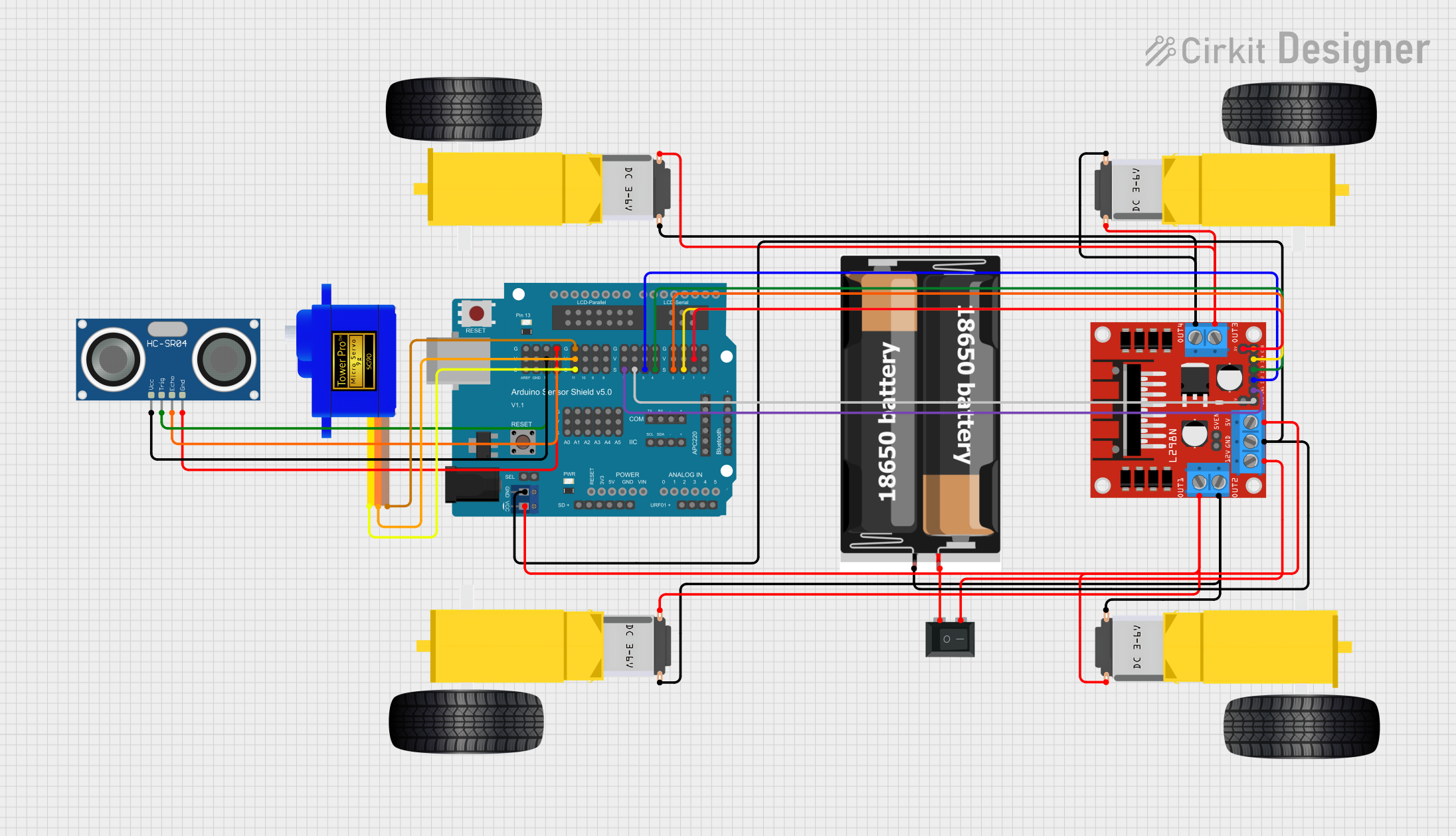
Arduino-Controlled Obstacle Avoiding Robot with Ultrasonic Sensor and L298N Motor Driver
This is a mobile robot platform controlled by an Arduino UNO with a sensor shield. It uses an HC-SR04 ultrasonic sensor for obstacle detection and a servo motor for directional control. The robot's movement is powered by gearmotors controlled by an L298N motor driver, and it is designed to navigate by avoiding obstacles detected by the ultrasonic sensor.
Common Applications and Use Cases
- Robotics: Controlling the movement of robotic arms, wheels, and other components.
- Automated Systems: Managing conveyor belts, automated doors, and other machinery.
- DIY Projects: Building remote-controlled cars, drones, and other hobbyist projects.
- Educational Purposes: Teaching motor control and electronics in academic settings.
Technical Specifications
Key Technical Details
| Specification | Value |
|---|---|
| Operating Voltage | 5V - 12V |
| Motor Channels | 2 or 4 (depending on model) |
| Current per Channel | Up to 1.2A continuous |
| Peak Current | 3A per channel (short duration) |
| Communication | I2C |
| Dimensions | 65mm x 56mm x 13mm |
Pin Configuration and Descriptions
Power and Control Pins
| Pin Name | Description |
|---|---|
| VIN | Power supply input (5V - 12V) |
| GND | Ground |
| SDA | I2C data line |
| SCL | I2C clock line |
| M1+ | Motor 1 positive terminal |
| M1- | Motor 1 negative terminal |
| M2+ | Motor 2 positive terminal |
| M2- | Motor 2 negative terminal |
Additional Pins (if applicable)
| Pin Name | Description |
|---|---|
| M3+ | Motor 3 positive terminal |
| M3- | Motor 3 negative terminal |
| M4+ | Motor 4 positive terminal |
| M4- | Motor 4 negative terminal |
Usage Instructions
How to Use the Motor Hat in a Circuit
Power Supply:
- Connect the VIN pin to a power source (5V - 12V).
- Connect the GND pin to the ground of the power source.
Motor Connections:
- Connect the motors to the respective motor terminals (M1+, M1-, M2+, M2-, etc.).
Microcontroller Interface:
- Connect the SDA pin to the I2C data line of the microcontroller.
- Connect the SCL pin to the I2C clock line of the microcontroller.
Programming:
- Use the appropriate library for your microcontroller to control the motors via I2C.
Important Considerations and Best Practices
- Power Supply: Ensure that the power supply voltage matches the requirements of both the Motor Hat and the motors.
- Current Limits: Do not exceed the current ratings to avoid damaging the Motor Hat.
- Heat Dissipation: Provide adequate cooling if the motors are running at high currents for extended periods.
- I2C Address: Check and set the correct I2C address if using multiple I2C devices.
Example Code for Arduino UNO
#include <Wire.h>
#include <Adafruit_MotorShield.h>

// Create the motor shield object with the default I2C address
Adafruit_MotorShield AFMS = Adafruit_MotorShield();

// Connect a DC motor to port M1
Adafruit_DCMotor *myMotor = AFMS.getMotor(1);

void setup() {
  Serial.begin(9600);           // Set up serial communication at 9600 baud
  Serial.println("Adafruit Motorshield v2 - DC Motor test!");

  AFMS.begin();  // Create with the default frequency 1.6KHz

  myMotor->setSpeed(150); // Set the speed to 150 out of 255
  myMotor->run(FORWARD);  // Turn on the motor in forward direction
}

void loop() {
  myMotor->run(FORWARD);  // Run the motor forward
  delay(1000);            // Wait for 1 second

  myMotor->run(BACKWARD); // Run the motor backward
  delay(1000);            // Wait for 1 second

  myMotor->run(RELEASE);  // Stop the motor
  delay(1000);            // Wait for 1 second
}
Troubleshooting and FAQs
Common Issues Users Might Face
Motor Not Running:
- Solution: Check power connections and ensure the power supply is adequate. Verify motor connections and I2C communication.
Overheating:
- Solution: Ensure the current does not exceed the rated limits. Provide adequate cooling or heat sinks.
I2C Communication Failure:
- Solution: Check the SDA and SCL connections. Ensure the correct I2C address is used.
Solutions and Tips for Troubleshooting
- Check Connections: Ensure all connections are secure and correctly placed.
- Use a Multimeter: Verify voltage levels and continuity of connections.
- Consult Datasheets: Refer to the datasheets of the Motor Hat and motors for detailed specifications and guidelines.
- Library Documentation: Use the official libraries and refer to their documentation for proper usage.
By following this documentation, users can effectively utilize the Motor Hat in their projects, ensuring reliable and efficient motor control.