How to Use RJ45 Cat6 T568B Connectors: Examples, Pinouts, and Specs
Introduction
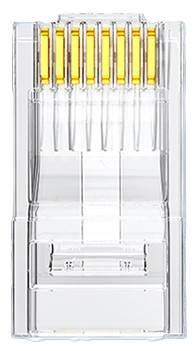
RJ45 Cat6 T568B Connectors are modular connectors used for terminating Ethernet cables, specifically designed for high-speed data transmission in networking applications. These connectors adhere to the T568B wiring standard, ensuring proper pin configuration for optimal performance. They are widely used in Ethernet networks, including home, office, and industrial environments, to establish reliable connections for data, voice, and video communication.
Explore Projects Built with RJ45 Cat6 T568B Connectors

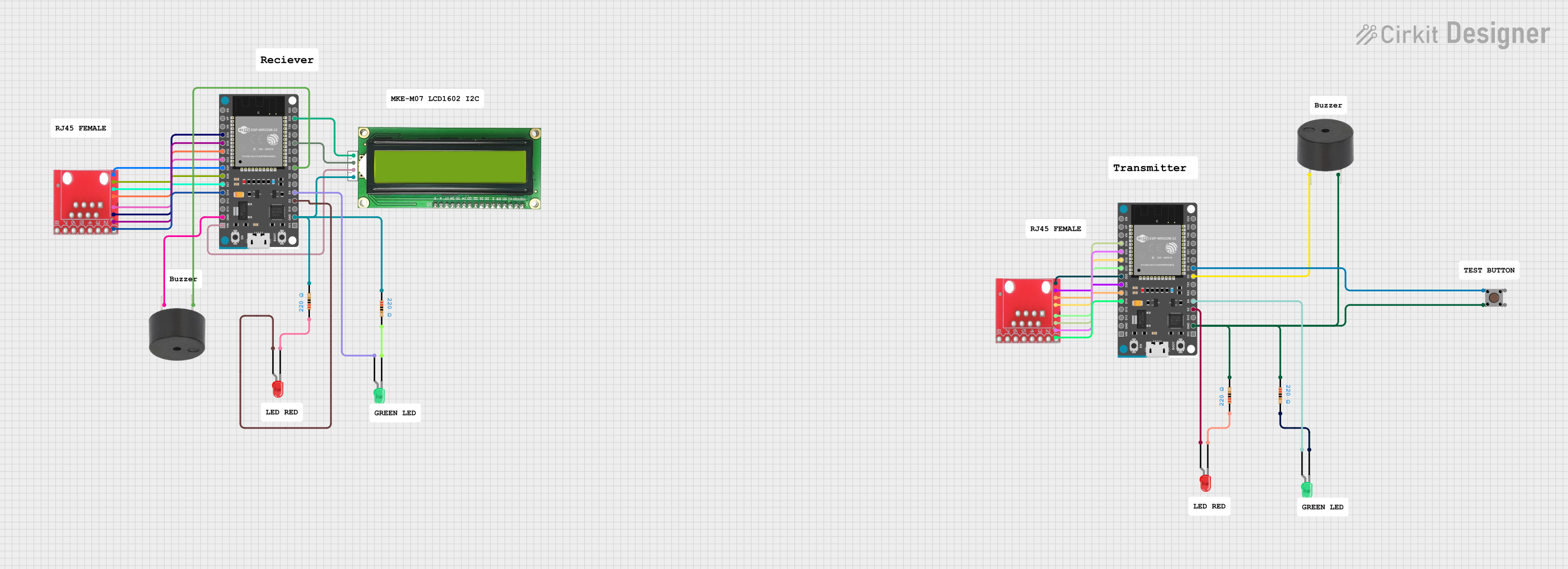


Explore Projects Built with RJ45 Cat6 T568B Connectors
Common Applications and Use Cases
- Terminating Cat6 Ethernet cables for networking
- Connecting devices such as routers, switches, and computers
- Structured cabling in residential, commercial, and industrial setups
- High-speed data transmission for Gigabit Ethernet and beyond
- VoIP (Voice over IP) and video streaming applications
Technical Specifications
Key Technical Details
- Connector Type: RJ45 (8P8C - 8 positions, 8 contacts)
- Cable Compatibility: Cat6 Ethernet cables (23-24 AWG)
- Wiring Standard: T568B
- Supported Speeds: Up to 10 Gbps (Gigabit Ethernet)
- Material: Gold-plated contacts for corrosion resistance and improved conductivity
- Operating Temperature: -40°C to 85°C
- Durability: Rated for 750+ mating cycles
Pin Configuration and Descriptions
The RJ45 Cat6 T568B Connector uses the T568B wiring standard, which defines the pinout for Ethernet cables. Below is the pin configuration:
| Pin Number | Wire Color (T568B Standard) | Signal Description |
|---|---|---|
| 1 | White/Orange | Transmit Data + (TX+) |
| 2 | Orange | Transmit Data - (TX-) |
| 3 | White/Green | Receive Data + (RX+) |
| 4 | Blue | Unused (Power over Ethernet - Positive) |
| 5 | White/Blue | Unused (Power over Ethernet - Positive) |
| 6 | Green | Receive Data - (RX-) |
| 7 | White/Brown | Unused (Power over Ethernet - Negative) |
| 8 | Brown | Unused (Power over Ethernet - Negative) |
Usage Instructions
How to Use the Component in a Circuit
Prepare the Ethernet Cable:
- Strip approximately 1 inch of the outer jacket of the Cat6 cable.
- Untwist the wire pairs and arrange them according to the T568B wiring standard.
Insert Wires into the Connector:
- Align the wires in the correct order (refer to the pin configuration table).
- Trim the wires to ensure they are even and fit snugly into the connector.
Crimp the Connector:
- Insert the wires into the RJ45 connector until they reach the end.
- Use an RJ45 crimping tool to secure the connector to the cable.
Test the Connection:
- Use a cable tester to verify the continuity and correct pinout of the terminated cable.
Important Considerations and Best Practices
- Ensure the wires are fully inserted into the connector to avoid poor connections.
- Use high-quality crimping tools to prevent damage to the connector or cable.
- Follow the T568B wiring standard consistently to maintain compatibility across devices.
- Avoid excessive bending or twisting of the cable to preserve signal integrity.
- If using Power over Ethernet (PoE), ensure the connector and cable meet the required specifications.
Example: Connecting to an Arduino UNO
While RJ45 connectors are not directly compatible with an Arduino UNO, you can use an Ethernet shield to interface with the Arduino. Below is an example code snippet for using an Ethernet shield with an RJ45-terminated cable:
#include <SPI.h>
#include <Ethernet.h>

// MAC address and IP address for the Ethernet shield
byte mac[] = { 0xDE, 0xAD, 0xBE, 0xEF, 0xFE, 0xED };
IPAddress ip(192, 168, 1, 177);

// Initialize the Ethernet server on port 80
EthernetServer server(80);

void setup() {
  // Start the Ethernet connection
  Ethernet.begin(mac, ip);
  // Start the server
  server.begin();
  Serial.begin(9600);
  Serial.println("Server is ready at IP: ");
  Serial.println(Ethernet.localIP());
}

void loop() {
  // Listen for incoming clients
  EthernetClient client = server.available();
  if (client) {
    Serial.println("New client connected");
    // Send a response to the client
    client.println("Hello from Arduino Ethernet Shield!");
    delay(100);
    client.stop();
  }
}
Troubleshooting and FAQs
Common Issues Users Might Face
Poor Connection or No Signal:
- Cause: Wires not fully inserted into the connector or incorrect wiring order.
- Solution: Re-terminate the cable, ensuring proper wire alignment and insertion.
Cable Tester Shows Incorrect Pinout:
- Cause: Wires arranged in the wrong order.
- Solution: Follow the T568B wiring standard carefully during termination.
Intermittent Connectivity:
- Cause: Loose crimping or damaged connector.
- Solution: Use a high-quality crimping tool and inspect the connector for damage.
Signal Degradation Over Long Distances:
- Cause: Exceeding the maximum cable length for Cat6 (100 meters).
- Solution: Use a network switch or repeater to extend the range.
Solutions and Tips for Troubleshooting
- Always test the cable with a cable tester after termination.
- Use high-quality Cat6 cables and connectors to ensure optimal performance.
- Avoid running Ethernet cables near power lines or sources of electromagnetic interference.
- If using PoE, ensure the power requirements of the connected device are within the supported range of the cable and connector.
By following these guidelines, you can effectively use RJ45 Cat6 T568B Connectors for reliable and high-speed networking applications.