How to Use Motor stepper & driver: Examples, Pinouts, and Specs
Introduction
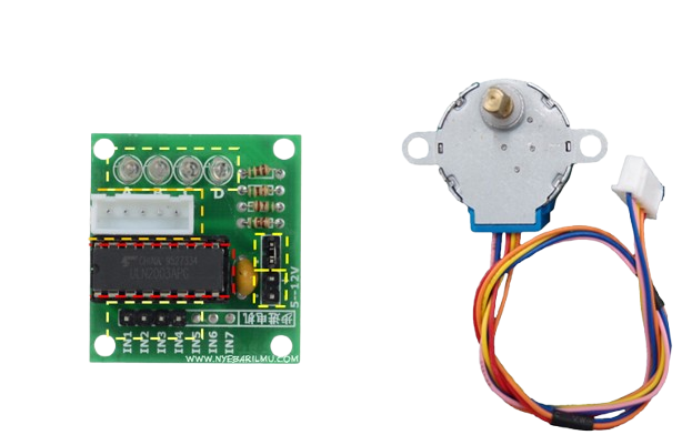
A stepper motor is a type of DC motor that divides a full rotation into a large number of steps, allowing for precise control of position and speed. The driver is an electronic circuit that controls the motor's operation, providing the necessary current and voltage to each coil in the motor to achieve accurate movement.
Stepper motors are widely used in applications requiring precise positioning, such as 3D printers, CNC machines, robotics, and camera gimbals. The combination of a stepper motor and its driver enables smooth and accurate motion control, making it ideal for both industrial and hobbyist projects.
Explore Projects Built with Motor stepper & driver
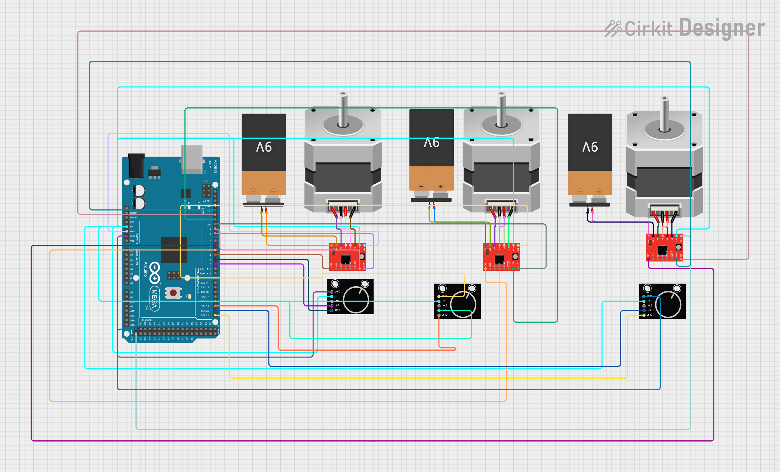

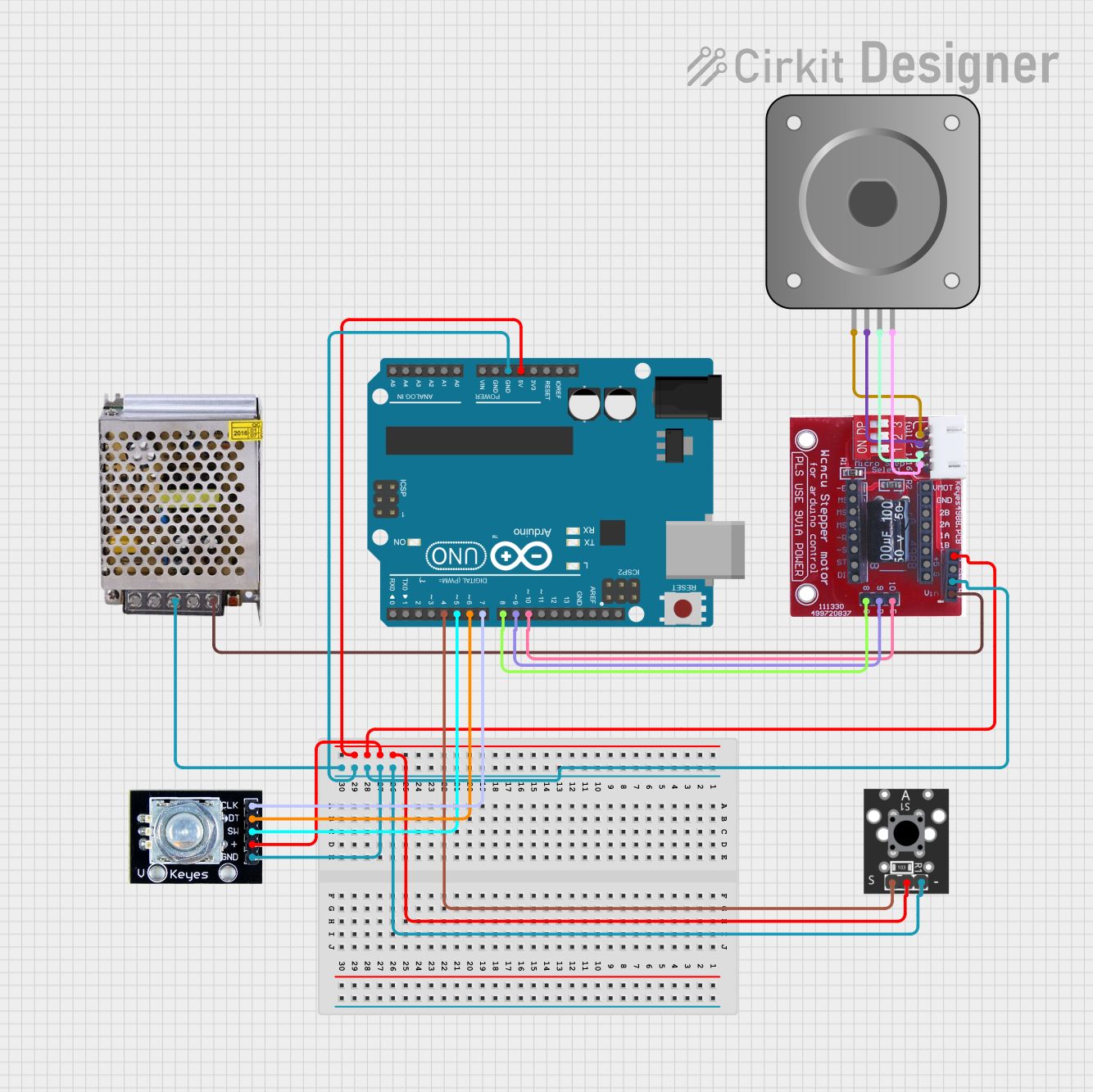
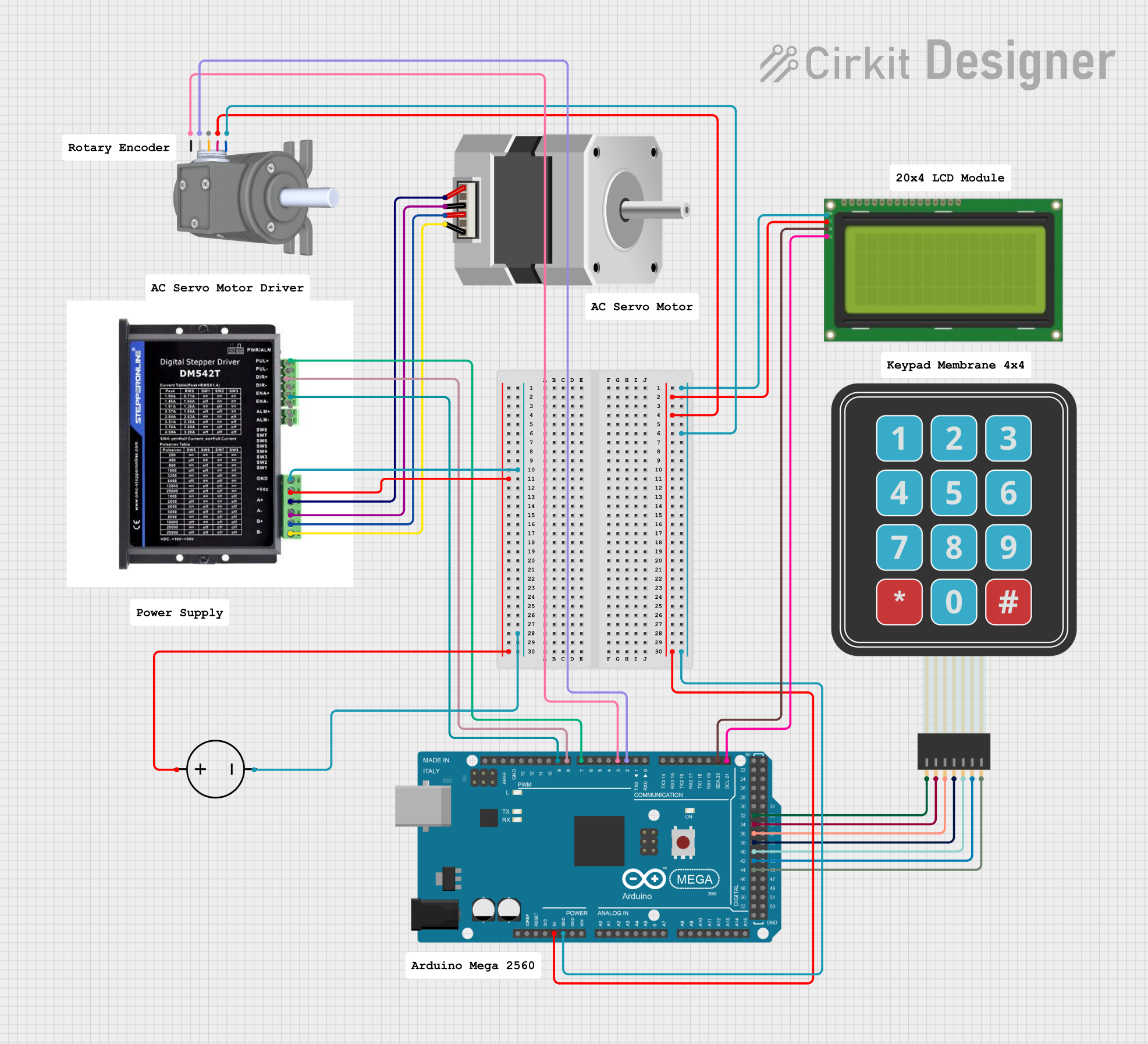
Explore Projects Built with Motor stepper & driver
Technical Specifications
Stepper Motor Specifications
| Parameter | Value |
|---|---|
| Motor Type | Bipolar or Unipolar |
| Step Angle | 1.8° (200 steps per rotation) |
| Voltage Range | 5V to 12V (varies by model) |
| Current per Phase | 1A to 2A (varies by model) |
| Holding Torque | 0.2 Nm to 1.5 Nm |
| Shaft Diameter | 5mm to 8mm |
Stepper Motor Driver Specifications
| Parameter | Value |
|---|---|
| Input Voltage | 8V to 35V |
| Output Current | Up to 2A per phase |
| Microstepping Support | Full, Half, 1/4, 1/8, 1/16 |
| Logic Voltage | 3.3V or 5V |
| Control Interface | Step and Direction pins |
| Protection Features | Overcurrent, Overtemperature |
Pin Configuration for Common Stepper Motor Drivers (e.g., A4988)
| Pin Name | Description |
|---|---|
| VMOT | Motor power supply (8V to 35V) |
| GND | Ground connection |
| VDD | Logic power supply (3.3V or 5V) |
| STEP | Step pulse input (controls motor steps) |
| DIR | Direction input (controls rotation direction) |
| ENABLE | Enable/disable motor driver (active low) |
| MS1, MS2, MS3 | Microstepping mode selection (set to HIGH/LOW for desired microstepping) |
| OUT1A, OUT1B | Outputs for motor coil 1 |
| OUT2A, OUT2B | Outputs for motor coil 2 |
Usage Instructions
Connecting the Stepper Motor and Driver
- Power Supply: Connect the motor power supply (VMOT) and ground (GND) to the driver. Ensure the voltage matches the motor's requirements.
- Logic Power: Connect the logic power supply (VDD) and ground (GND) to the driver. Use 3.3V or 5V depending on your microcontroller.
- Motor Coils: Connect the stepper motor's coils to the driver outputs (OUT1A, OUT1B, OUT2A, OUT2B). Refer to the motor's datasheet for coil wiring.
- Control Pins: Connect the STEP and DIR pins to your microcontroller's GPIO pins. Optionally, connect ENABLE and microstepping pins (MS1, MS2, MS3) as needed.
Arduino UNO Example Code
Below is an example of how to control a stepper motor using an A4988 driver and an Arduino UNO:
// Define control pins for the stepper motor driver
#define STEP_PIN 3  // Pin connected to STEP on the driver
#define DIR_PIN 4   // Pin connected to DIR on the driver

void setup() {
  pinMode(STEP_PIN, OUTPUT); // Set STEP pin as output
  pinMode(DIR_PIN, OUTPUT);  // Set DIR pin as output

  digitalWrite(DIR_PIN, HIGH); // Set initial direction (HIGH = clockwise)
}

void loop() {
  // Rotate the motor one step at a time
  digitalWrite(STEP_PIN, HIGH); // Generate a step pulse
  delayMicroseconds(1000);      // Wait for 1ms (adjust for speed control)
  digitalWrite(STEP_PIN, LOW);  // End the step pulse
  delayMicroseconds(1000);      // Wait for 1ms before the next step
}
Important Considerations
- Current Limiting: Adjust the current limit on the driver to match the motor's rated current. This prevents overheating and damage.
- Microstepping: Use the MS1, MS2, and MS3 pins to configure microstepping for smoother motion.
- Heat Dissipation: Ensure proper cooling for the driver, especially at high currents. Use a heatsink or fan if necessary.
- Power Supply: Use a stable power supply with sufficient current capacity for both the motor and driver.
Troubleshooting and FAQs
Common Issues and Solutions
Motor Not Moving:
- Check all connections, especially the motor coils and power supply.
- Verify that the STEP and DIR pins are receiving signals from the microcontroller.
- Ensure the driver is enabled (ENABLE pin is LOW).
Motor Vibrates but Doesn't Rotate:
- Verify the wiring of the motor coils. Incorrect wiring can cause erratic behavior.
- Check the microstepping configuration and ensure it matches your setup.
Driver Overheating:
- Reduce the current limit on the driver.
- Add a heatsink or fan for better heat dissipation.
Inconsistent or Jerky Motion:
- Ensure the STEP signal timing is consistent. Use delays or timers in your code.
- Check for loose connections or faulty wiring.
FAQs
Q: Can I use a unipolar stepper motor with a bipolar driver?
A: Yes, you can use a unipolar motor as a bipolar motor by ignoring the center tap wires and connecting only the end wires of each coil.
Q: How do I calculate the required power supply for my motor?
A: Multiply the motor's rated voltage by its current per phase, then add a safety margin of 20-30%.
Q: What is microstepping, and why is it important?
A: Microstepping divides each full step into smaller steps, providing smoother motion and higher resolution. It reduces vibration and noise in the motor.
Q: Can I control multiple stepper motors with one Arduino?
A: Yes, you can control multiple motors by assigning separate STEP and DIR pins for each motor. Ensure the Arduino has enough GPIO pins and processing power for your application.