How to Use KONTAKTOR: Examples, Pinouts, and Specs
Introduction
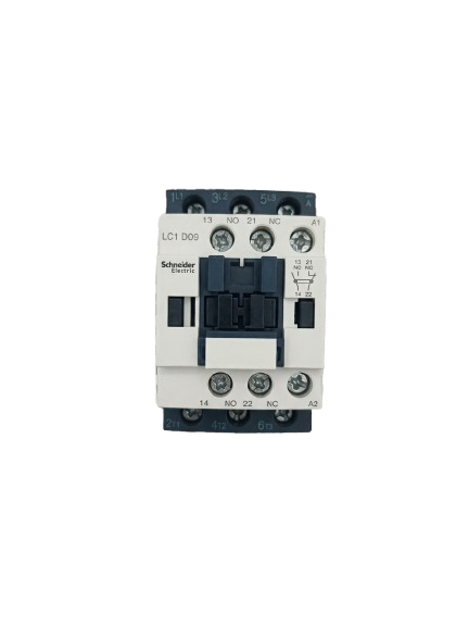
A kontaktor, or contactor, is an electromechanical switch designed to control high-power circuits using low-power signals. It operates by utilizing an electromagnet to open or close its contacts, enabling or interrupting the flow of electricity in the controlled circuit. Kontaktors are widely used in industrial and commercial applications due to their reliability and ability to handle high currents.
Explore Projects Built with KONTAKTOR


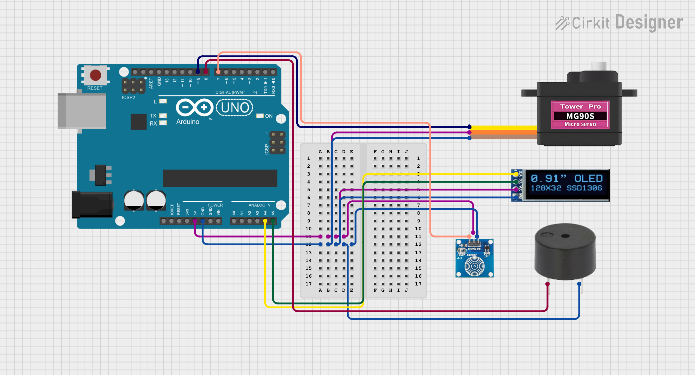
Explore Projects Built with KONTAKTOR
Common Applications and Use Cases
- Motor control in industrial machinery
- Lighting systems in commercial buildings
- HVAC (Heating, Ventilation, and Air Conditioning) systems
- Power distribution and automation systems
- Electric vehicle charging stations
Technical Specifications
Key Technical Details
| Parameter | Value/Range |
|---|---|
| Coil Voltage | 12V, 24V, 48V, 110V, 220V AC/DC |
| Contact Voltage Rating | Up to 1000V AC/DC |
| Contact Current Rating | 10A to 600A (varies by model) |
| Number of Poles | 1P, 2P, 3P, or 4P |
| Mechanical Life | Up to 10 million operations |
| Electrical Life | Up to 1 million operations |
| Operating Temperature | -25°C to +55°C |
| Mounting Type | DIN rail or panel-mounted |
Pin Configuration and Descriptions
| Pin/Terminal Label | Description |
|---|---|
| A1, A2 | Coil terminals: Connect the low-power control signal to these terminals. |
| L1, L2, L3 | Input terminals: Connect the high-power input lines (for 3-phase systems). |
| T1, T2, T3 | Output terminals: Connect the high-power load (e.g., motor, lighting). |
| NO (Normally Open) | Auxiliary contact: Open by default, closes when the coil is energized. |
| NC (Normally Closed) | Auxiliary contact: Closed by default, opens when the coil is energized. |
Usage Instructions
How to Use the Component in a Circuit
- Determine the Coil Voltage: Verify the voltage required to energize the coil (e.g., 24V DC or 220V AC).
- Connect the Coil Terminals: Attach the control signal to the A1 and A2 terminals. Ensure the control voltage matches the coil rating.
- Connect the Power Circuit:
- For single-phase systems, connect the input power line to L1 and the load to T1.
- For three-phase systems, connect the input power lines to L1, L2, L3 and the load to T1, T2, T3.
- Use Auxiliary Contacts (if needed): Auxiliary contacts (NO/NC) can be used for signaling or interlocking purposes.
- Secure the Kontaktor: Mount the kontaktor on a DIN rail or panel as per the installation requirements.
Important Considerations and Best Practices
- Overcurrent Protection: Always use appropriate fuses or circuit breakers to protect the circuit.
- Voltage Matching: Ensure the coil voltage matches the control signal and the contact voltage matches the load.
- Avoid Overheating: Do not exceed the rated current or voltage to prevent overheating and damage.
- Noise Suppression: Use a snubber circuit or diode across the coil terminals to suppress voltage spikes.
- Periodic Maintenance: Inspect the contacts periodically for wear and clean them if necessary.
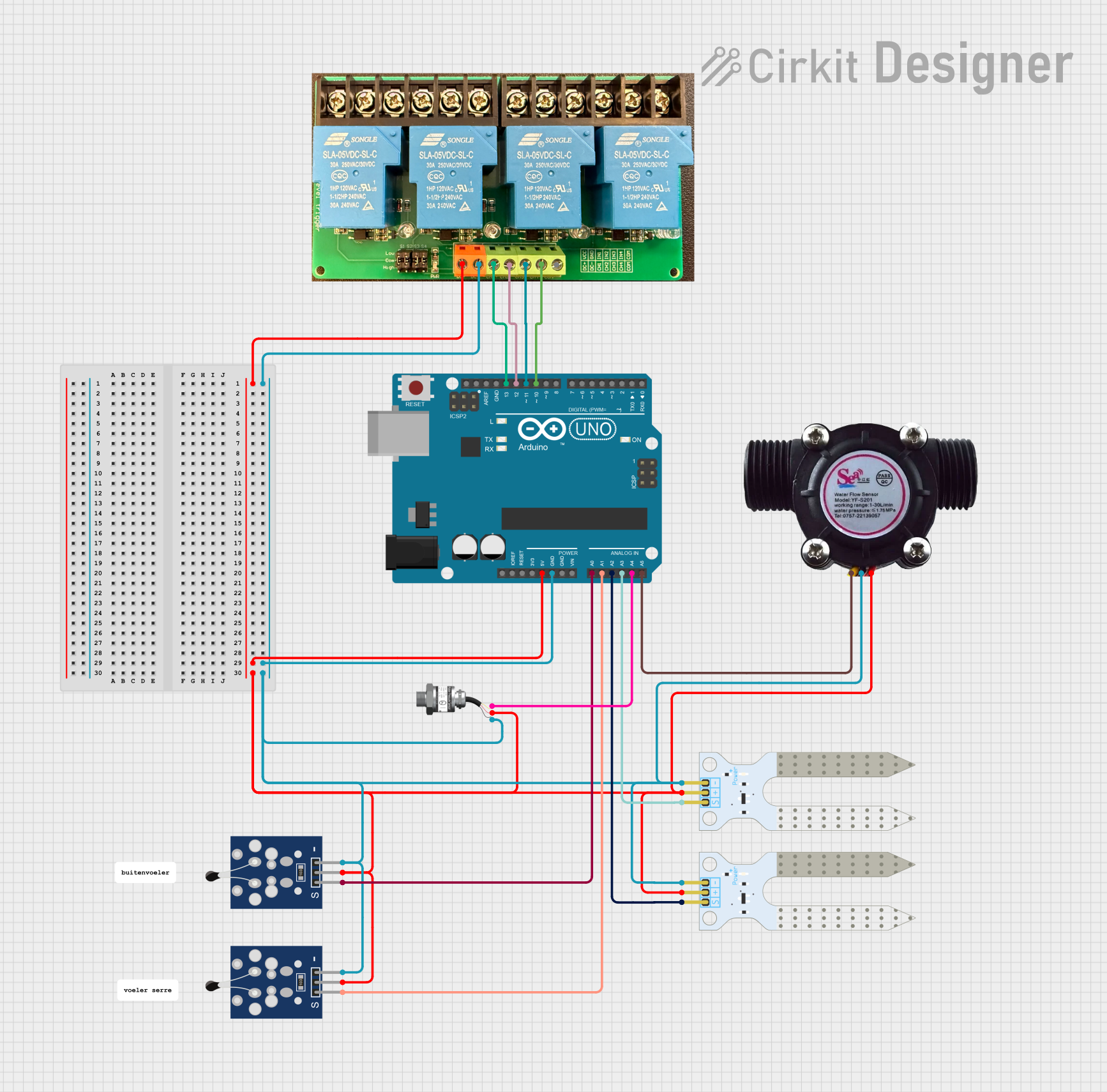
Example: Connecting a Kontaktor to an Arduino UNO
Below is an example of controlling a 24V DC kontaktor using an Arduino UNO and a relay module.
// Example: Controlling a 24V DC Kontaktor with Arduino UNO
// This code energizes the kontaktor coil for 5 seconds, then de-energizes it.

const int relayPin = 7; // Pin connected to the relay module

void setup() {
  pinMode(relayPin, OUTPUT); // Set relay pin as output
  digitalWrite(relayPin, LOW); // Ensure relay is off initially
}

void loop() {
  digitalWrite(relayPin, HIGH); // Energize the relay (and the kontaktor coil)
  delay(5000); // Keep the coil energized for 5 seconds
  digitalWrite(relayPin, LOW); // De-energize the relay (and the kontaktor coil)
  delay(5000); // Wait for 5 seconds before repeating
}
Note: Ensure the relay module is rated to handle the coil current of the kontaktor. Use an external power supply for the coil if necessary.
Troubleshooting and FAQs
Common Issues and Solutions
| Issue | Possible Cause | Solution |
|---|---|---|
| Kontaktor does not energize | Incorrect coil voltage | Verify and match the control voltage. |
| Contacts do not close/open properly | Worn or damaged contacts | Inspect and replace the contacts. |
| Excessive noise or arcing | Overvoltage or inductive load issues | Use a snubber circuit or RC filter. |
| Coil overheating | Prolonged energization or overvoltage | Check the duty cycle and voltage rating. |
| Auxiliary contacts not functioning | Miswiring or mechanical failure | Verify wiring and inspect the mechanism. |
FAQs
Can I use a kontaktor for DC loads? Yes, but ensure the kontaktor is rated for DC operation, as DC arcs are harder to extinguish than AC arcs.
What is the difference between a relay and a kontaktor? A relay is typically used for low-power applications, while a kontaktor is designed for high-power circuits.
How do I reduce coil noise in a kontaktor? Use a diode (for DC coils) or an RC snubber (for AC coils) across the coil terminals to suppress noise.
Can I control a kontaktor directly with an Arduino? No, the Arduino cannot supply sufficient current to energize the coil. Use a relay module or transistor circuit as an intermediary.
By following this documentation, you can effectively integrate and troubleshoot a kontaktor in your electrical or automation projects.