How to Use Current Sensor 5A: Examples, Pinouts, and Specs
Introduction
The Current Sensor 5A is an electronic device designed to measure the flow of electric current in a conductor. This sensor can measure currents up to 5 amperes, making it suitable for a wide range of applications, including power supply monitoring, battery management, and load detection in consumer electronics, automotive systems, and industrial equipment.
Explore Projects Built with Current Sensor 5A


Explore Projects Built with Current Sensor 5A
Common Applications and Use Cases
- Battery Chargers: Monitoring charge and discharge currents.
- Energy Monitoring: Measuring power consumption in appliances.
- Overcurrent Protection: Detecting and responding to excessive current draw.
- Motor Control: Assessing motor current for performance and safety.
Technical Specifications
Key Technical Details
- Measurement Range: 0 to 5A
- Supply Voltage: Typically 5V to 12V
- Output Type: Analog voltage proportional to measured current
- Sensitivity: Typically around 185 mV/A
- Accuracy: ±1.5% (typical, at 25°C)
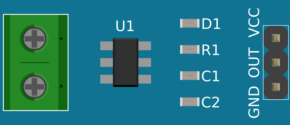
Pin Configuration and Descriptions
| Pin Number | Name | Description |
|---|---|---|
| 1 | Vcc | Power supply input, typically 5V to 12V |
| 2 | Out | Analog output voltage proportional to the current |
| 3 | GND | Ground reference for the power supply |
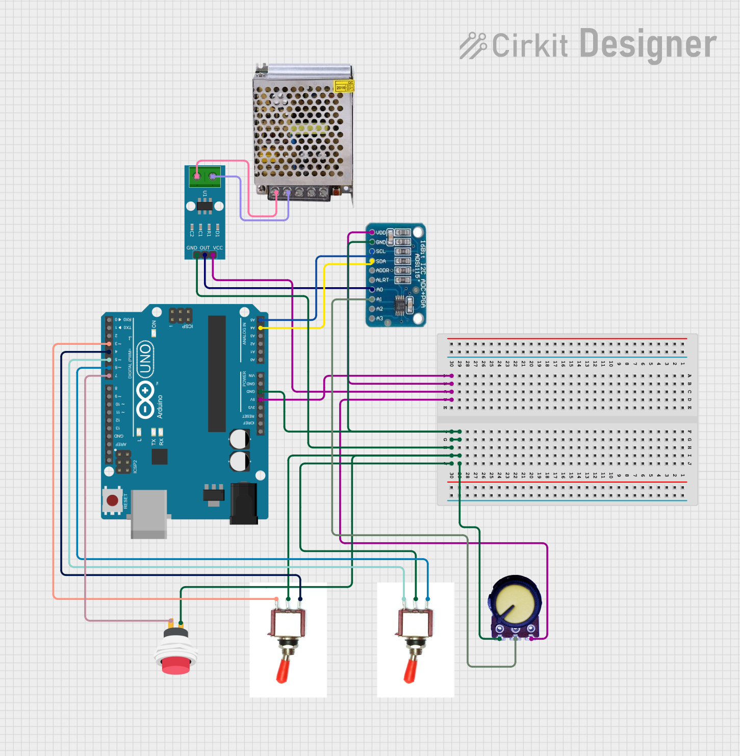
Usage Instructions
How to Use the Component in a Circuit
- Power Supply: Connect the Vcc pin to a power supply within the specified voltage range.
- Ground Connection: Connect the GND pin to the ground of your circuit.
- Current Measurement: Pass the conductor carrying the current to be measured through the sensor's current path.
- Analog Reading: Connect the Out pin to an analog input on your microcontroller to read the voltage output.
Important Considerations and Best Practices
- Calibration: Calibrate the sensor for accurate readings by comparing its output to a known current source.
- Noise Reduction: Use a low-pass filter or smoothing algorithm to reduce noise in the analog signal.
- Thermal Considerations: Avoid exposing the sensor to temperatures outside its specified range to prevent damage or drift in readings.
- Safety: Ensure that the current does not exceed the sensor's maximum rating to prevent damage.
Example Code for Arduino UNO
// Define the analog input pin connected to the sensor output
const int currentSensorPin = A0;

void setup() {
  // Initialize serial communication at 9600 baud rate
  Serial.begin(9600);
}

void loop() {
  // Read the sensor output voltage
  int sensorValue = analogRead(currentSensorPin);

  // Convert the sensor value to current (Amps)
  float current = (sensorValue * (5.0 / 1023.0)) / 0.185;

  // Print the current value to the Serial Monitor
  Serial.print("Current: ");
  Serial.print(current);
  Serial.println(" A");

  // Wait for a short period before reading again
  delay(500);
}
Troubleshooting and FAQs
Common Issues Users Might Face
- Inaccurate Readings: If the sensor provides inaccurate readings, recalibrate the sensor and check for proper power supply voltage.
- No Output: Ensure all connections are secure and the conductor is properly placed through the sensor.
- Noise in Signal: Implement a low-pass filter or increase the sample and hold time in your code to reduce noise.
Solutions and Tips for Troubleshooting
- Calibration: Use a multimeter to measure a known current and adjust the sensitivity in the code accordingly.
- Connection Check: Verify that the sensor's pins are correctly connected to the microcontroller and power supply.
- Signal Smoothing: Use software-based smoothing techniques like moving average or exponential smoothing to reduce noise.
FAQs
Q: Can the sensor measure AC current? A: This sensor is typically designed for DC current measurement. For AC current, a different sensor or additional circuitry may be required.
Q: What is the maximum voltage that can be applied to Vcc? A: The maximum voltage for Vcc should not exceed the specified range in the technical specifications, typically 12V.
Q: How can I increase the measurement range beyond 5A? A: To measure currents higher than 5A, you would need a sensor with a higher current rating or use a shunt resistor with a known value and measure the voltage drop across it.