How to Use usb-c famale connector: Examples, Pinouts, and Specs
Introduction
The USB-C female connector is a versatile and widely adopted interface designed for connecting USB-C cables and devices. It features a reversible design, allowing users to insert the connector in either orientation, eliminating frustration during connection. This connector supports high-speed data transfer, power delivery, and video output, making it a key component in modern electronics.
Explore Projects Built with usb-c famale connector


Explore Projects Built with usb-c famale connector
Common Applications and Use Cases
- Smartphones and Tablets: Used for charging, data transfer, and audio/video output.
- Laptops and Desktops: Enables high-speed data transfer, power delivery, and external display connections.
- Peripheral Devices: Found in external hard drives, docking stations, and USB hubs.
- Embedded Systems: Used in custom electronics projects for power and data interfacing.
Technical Specifications
The USB-C female connector adheres to the USB Type-C standard, offering robust performance and compatibility with a wide range of devices.
Key Technical Details
- Manufacturer: USB Type C
- Part ID: USB Type C
- Voltage Rating: Up to 20V (for USB Power Delivery)
- Current Rating: Up to 5A (depending on cable and device compatibility)
- Data Transfer Speeds: Up to 10Gbps (USB 3.1 Gen 2) or higher for newer standards
- Operating Temperature: -40°C to 85°C
- Durability: Rated for 10,000 insertion/removal cycles
- Pin Count: 24 pins
Pin Configuration and Descriptions
The USB-C female connector has 24 pins, symmetrically arranged to support its reversible design. Below is a simplified pinout table:
| Pin Name | Description | Notes |
|---|---|---|
| GND | Ground | Common ground for power and signals |
| VBUS | Power Supply | Provides power (up to 20V, 5A) |
| CC1, CC2 | Configuration Channel | Used for cable orientation and power negotiation |
| D+, D- | USB 2.0 Data Lines | Legacy USB 2.0 data transfer |
| TX1+, TX1- | SuperSpeed Differential Pair 1 | High-speed data transfer (TX direction) |
| RX1+, RX1- | SuperSpeed Differential Pair 2 | High-speed data transfer (RX direction) |
| TX2+, TX2- | SuperSpeed Differential Pair 3 | High-speed data transfer (TX direction) |
| RX2+, RX2- | SuperSpeed Differential Pair 4 | High-speed data transfer (RX direction) |
| SBU1, SBU2 | Sideband Use | Used for alternate modes (e.g., audio) |
| Shield | Connector Shield | Provides EMI protection |
Usage Instructions
How to Use the USB-C Female Connector in a Circuit
- Soldering: The USB-C female connector is typically mounted on a PCB. Ensure proper alignment and solder all pins securely to avoid loose connections.
- Power Delivery: If using USB Power Delivery (PD), include a USB PD controller IC in your circuit to negotiate voltage and current levels with the connected device.
- Data Lines: Connect the D+, D-, and SuperSpeed differential pairs (TX/RX) to the appropriate data-handling ICs or microcontrollers.
- Configuration Channels (CC1, CC2): Use pull-up or pull-down resistors on the CC pins to indicate the power source or sink role of your device.
- Shielding: Connect the shield pin to the ground plane for improved electromagnetic interference (EMI) protection.
Important Considerations and Best Practices
- Reversible Design: Ensure both CC1 and CC2 pins are properly connected to handle the reversible nature of the connector.
- Power Delivery: Use appropriate overcurrent and overvoltage protection circuits to safeguard your device.
- High-Speed Signals: Route high-speed differential pairs (TX/RX) with controlled impedance to maintain signal integrity.
- Thermal Management: If using high power (e.g., 20V, 5A), ensure adequate thermal dissipation to prevent overheating.
Example: Connecting to an Arduino UNO
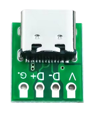
While the Arduino UNO does not natively support USB-C, you can use a USB-C breakout board to interface with it. Below is an example of using the USB-C connector for power input:
// Example: Using USB-C to power an Arduino UNO
// Connect the VBUS pin of the USB-C connector to the Arduino's VIN pin.
// Connect the GND pin of the USB-C connector to the Arduino's GND pin.

void setup() {
  // No specific setup required for power input
}

void loop() {
  // Your main code here
}
Troubleshooting and FAQs
Common Issues Users Might Face
- Loose Connections: Poor soldering can lead to intermittent connections.
- Solution: Re-solder the pins carefully, ensuring proper alignment and secure joints.
- Overheating: Excessive current draw can cause the connector to overheat.
- Solution: Verify that the connected device does not exceed the current rating of the connector.
- Data Transfer Issues: High-speed data transfer may fail due to improper routing of differential pairs.
- Solution: Ensure controlled impedance and minimize trace lengths for TX/RX pairs.
- Power Delivery Not Working: The device does not negotiate the correct voltage/current.
- Solution: Check the configuration of the CC pins and ensure the USB PD controller is functioning correctly.
FAQs
Q: Can I use the USB-C female connector for USB 2.0 devices?
A: Yes, the USB-C connector is backward compatible with USB 2.0. Use the D+ and D- pins for data transfer.Q: How do I handle the reversible nature of the connector?
A: Connect both CC1 and CC2 pins to ensure proper orientation detection.Q: What is the maximum power I can draw from this connector?
A: The connector supports up to 20V and 5A (100W) with USB Power Delivery, provided the cable and device are compatible.Q: Do I need to connect all 24 pins for basic functionality?
A: No, for basic power and USB 2.0 data transfer, only a subset of pins (VBUS, GND, D+, D-, CC) is required.
This documentation provides a comprehensive guide to understanding and using the USB-C female connector effectively in your projects.