How to Use 2 Channel 12v Relay: Examples, Pinouts, and Specs
Introduction
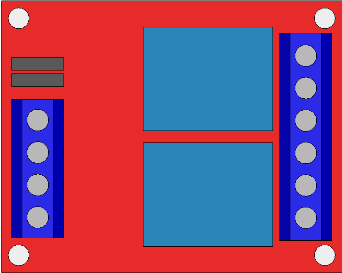
A 2 Channel 12V Relay Module is an electronic device that allows a low-power signal, often from a microcontroller like an Arduino, to control two separate high-power circuits. It acts as an electrically operated switch and is commonly used in automation projects, home appliances, and automotive electronics where controlling high voltage or high current devices is necessary.
Explore Projects Built with 2 Channel 12v Relay

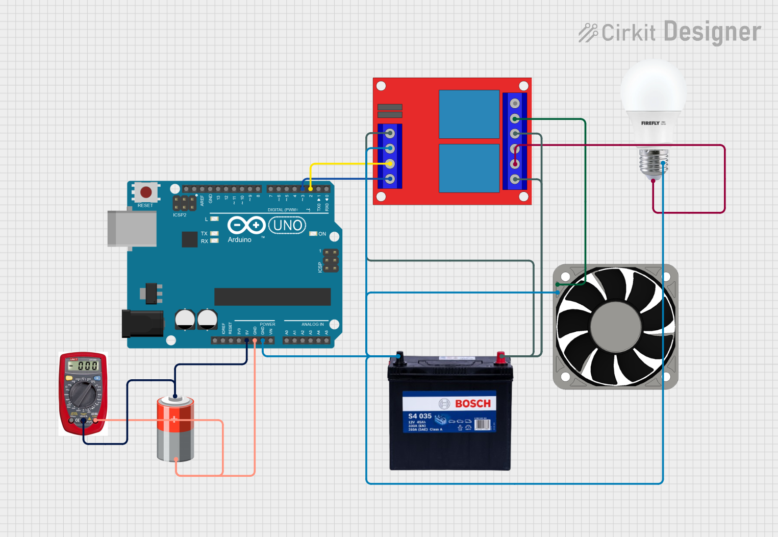

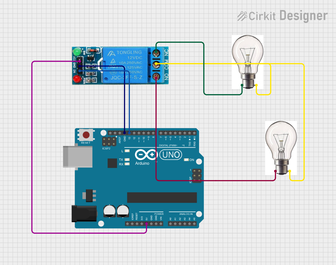
Explore Projects Built with 2 Channel 12v Relay
Common Applications and Use Cases
- Home automation systems
- Remote control switches
- Automotive electronics
- Robotics
- Power supply control
Technical Specifications
Key Technical Details
- Operating Voltage: 12V DC
- Trigger Voltage: 5V DC (from microcontroller)
- Switching Voltage: Up to 250V AC or 30V DC
- Switching Current: Up to 10A per channel
- Relay Life: 100,000 cycles (mechanical), 100,000,000 cycles (electrical at no load)
Pin Configuration and Descriptions
| Pin Number | Description | Type |
|---|---|---|
| 1 | VCC | Power |
| 2 | GND | Power |
| 3 | IN1 | Control |
| 4 | IN2 | Control |
| 5 | COM1 (Common 1) | Switch |
| 6 | NO1 (Normally Open 1) | Switch |
| 7 | NC1 (Normally Closed 1) | Switch |
| 8 | COM2 (Common 2) | Switch |
| 9 | NO2 (Normally Open 2) | Switch |
| 10 | NC2 (Normally Closed 2) | Switch |
Usage Instructions
How to Use the Component in a Circuit
Powering the Module:
- Connect the VCC pin to a 12V DC power supply.
- Connect the GND pin to the ground of the power supply.
Interfacing with a Microcontroller:
- Connect the IN1 and IN2 pins to digital output pins on the microcontroller.
- Ensure that the microcontroller's ground is connected to the GND pin of the relay module.
Connecting the Load:
- Connect the high-power circuit to the COM (Common) and NO (Normally Open) or NC (Normally Closed) pins, depending on whether you want the load to be powered when the relay is activated or not.
Important Considerations and Best Practices
- Isolation: Ensure proper isolation between the low-power control side and the high-power switch side to prevent electrical hazards.
- Inductive Loads: When controlling inductive loads (e.g., motors, solenoids), use a flyback diode to prevent voltage spikes.
- Power Supply: Use a stable 12V power supply to prevent relay chatter or failure to activate.
- Microcontroller Logic Levels: Ensure that the microcontroller's output logic levels are compatible with the relay's trigger voltage.
Troubleshooting and FAQs
Common Issues
- Relay Not Activating: Check the power supply voltage and connections. Ensure the control signal from the microcontroller is reaching the relay.
- Intermittent Operation: Verify that all connections are secure and that there is no loose wiring. Check for proper power supply stability.
- Noise Issues: Use snubber circuits or opto-isolators if there is interference from the high-power circuit affecting the low-power control circuit.
Solutions and Tips for Troubleshooting
- Check Connections: Double-check all wiring and solder joints.
- Test Power Supply: Use a multimeter to verify the voltage levels at VCC and GND.
- Signal Verification: Use an LED or multimeter to check if the control signal from the microcontroller is reaching the relay input pins.
FAQs
Q: Can I use this relay module with a 5V microcontroller? A: Yes, the trigger voltage is compatible with 5V logic levels.
Q: What is the difference between NO and NC? A: NO stands for Normally Open, meaning the relay's switch is open when not powered, and NC stands for Normally Closed, meaning the switch is closed when not powered.
Q: How many devices can I control with this relay module? A: You can control two separate devices, one per channel.
Example Arduino Code
// Define relay control pins
const int relayPin1 = 7;
const int relayPin2 = 8;

void setup() {
  // Set relay pins as output
  pinMode(relayPin1, OUTPUT);
  pinMode(relayPin2, OUTPUT);
}

void loop() {
  // Turn on relay 1
  digitalWrite(relayPin1, HIGH);
  delay(1000); // Wait for 1 second
  // Turn off relay 1
  digitalWrite(relayPin1, LOW);
  delay(1000); // Wait for 1 second

  // Turn on relay 2
  digitalWrite(relayPin2, HIGH);
  delay(1000); // Wait for 1 second
  // Turn off relay 2
  digitalWrite(relayPin2, LOW);
  delay(1000); // Wait for 1 second
}
Note: In the above code, HIGH is used to activate the relay, and LOW is used to deactivate it. This may vary depending on the relay module's design, so consult the module's datasheet for accurate information.