How to Use L298N: Examples, Pinouts, and Specs
Introduction
The L298N is a dual H-bridge motor driver IC designed to control the direction and speed of DC motors and stepper motors. It is widely used in robotics and automation projects due to its ability to drive two motors simultaneously with a maximum current of 2A per channel. The L298N is a versatile and cost-effective solution for motor control, making it a popular choice among hobbyists and professionals alike.
Explore Projects Built with L298N
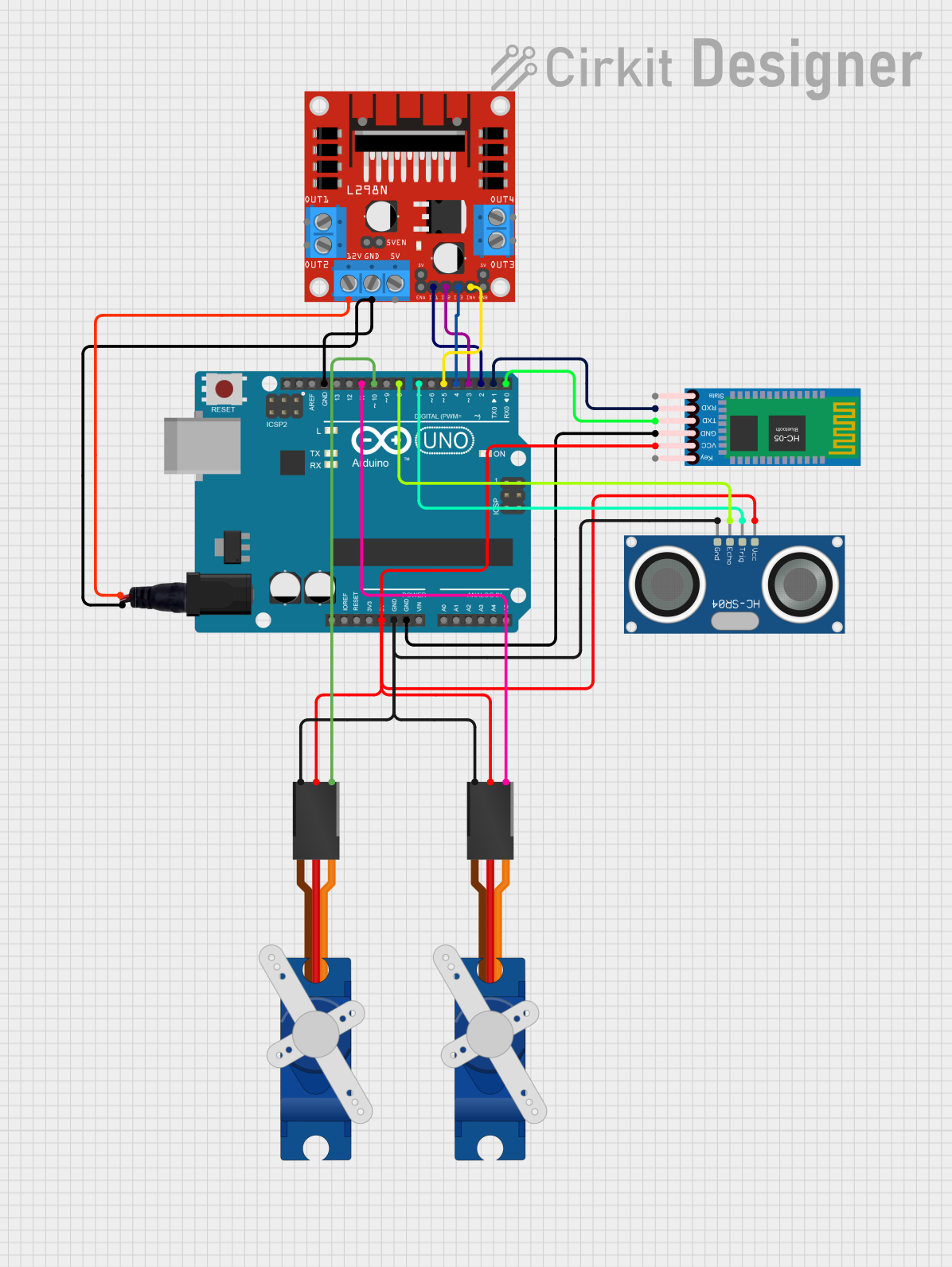
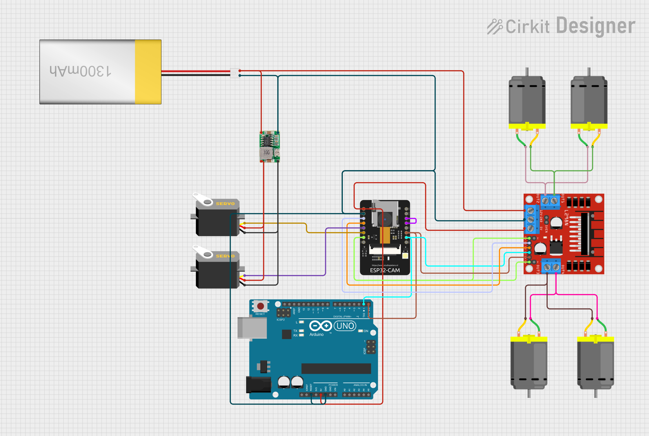
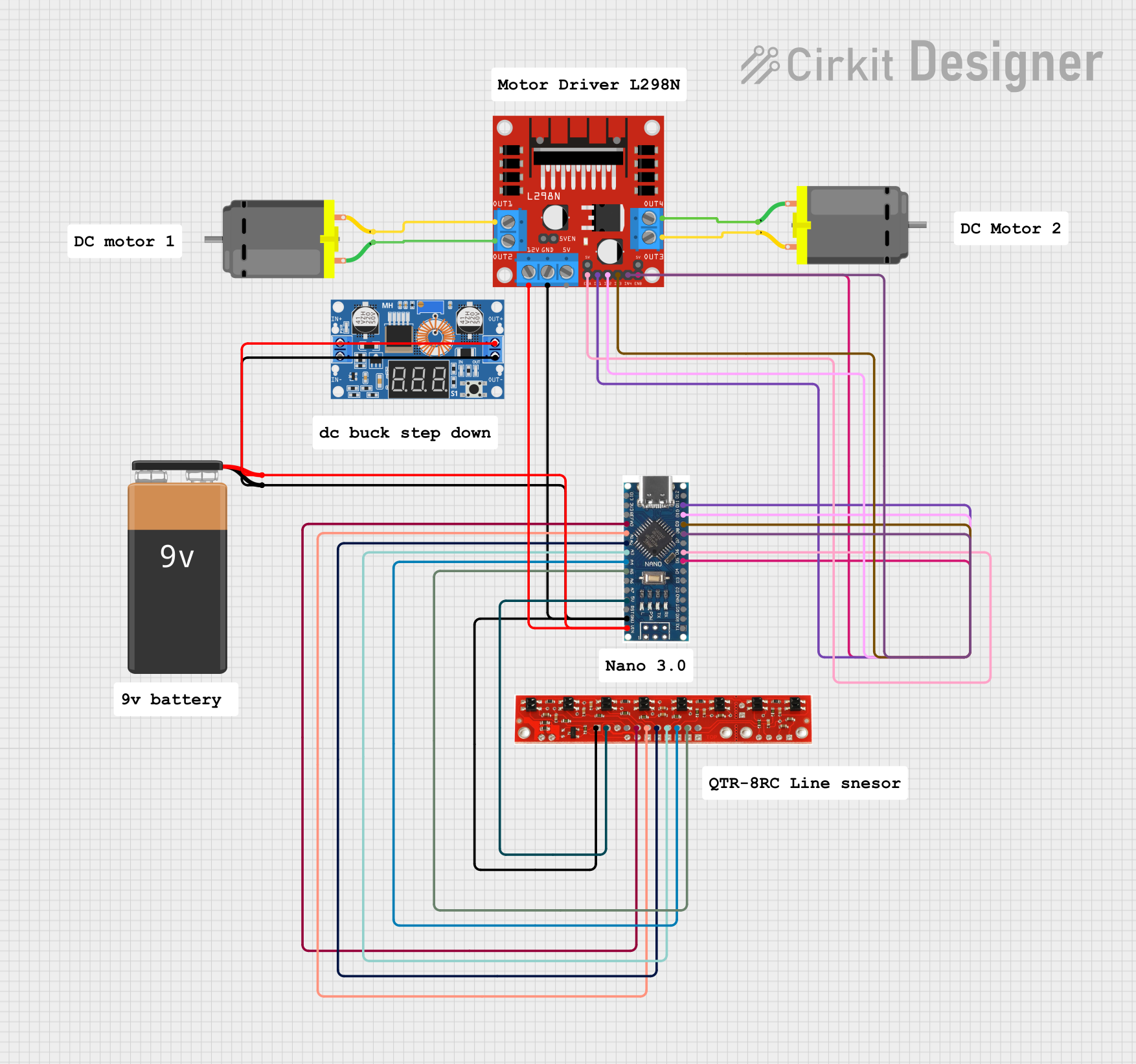

Explore Projects Built with L298N
Common Applications and Use Cases
- Robotics: Driving wheels or tracks of robots
- Automation: Controlling conveyor belts or actuators
- CNC machines: Operating stepper motors
- DIY projects: Building remote-controlled cars or robotic arms
Technical Specifications
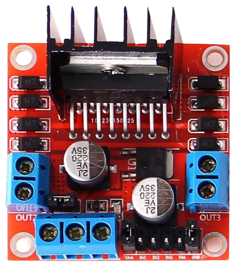
The L298N motor driver module is based on the L298N IC and typically includes additional components like a voltage regulator and terminal blocks for easy wiring. Below are the key technical details:
Key Specifications
- Operating Voltage (Logic): 5V
- Motor Supply Voltage (Vmotor): 5V to 35V
- Maximum Current (Per Channel): 2A
- Number of Channels: 2 (dual H-bridge)
- Control Logic Levels: TTL-compatible
- Power Dissipation: 25W (with proper heat sinking)
- Built-in Protection: Thermal shutdown and overcurrent protection
Pin Configuration and Descriptions
The L298N module typically has the following pins and terminals:
Control Pins
| Pin Name | Description |
|---|---|
| ENA | Enables motor A (PWM input for speed control) |
| IN1 | Input 1 for motor A (direction control) |
| IN2 | Input 2 for motor A (direction control) |
| ENB | Enables motor B (PWM input for speed control) |
| IN3 | Input 1 for motor B (direction control) |
| IN4 | Input 2 for motor B (direction control) |
Power and Motor Connections
| Pin Name | Description |
|---|---|
| VCC | Motor power supply (5V to 35V) |
| GND | Ground connection |
| 5V | Logic power supply (5V) |
| OUT1 | Output 1 for motor A |
| OUT2 | Output 2 for motor A |
| OUT3 | Output 1 for motor B |
| OUT4 | Output 2 for motor B |
Note: Some L298N modules include a jumper to enable the onboard 5V regulator. If the jumper is in place, the module can provide 5V logic power from the motor supply voltage.
Usage Instructions
How to Use the L298N in a Circuit
Power Connections:
- Connect the motor power supply to the
VCCpin (5V to 35V). - Connect the ground of the power supply to the
GNDpin. - If using the onboard 5V regulator, ensure the jumper is in place and use the
5Vpin for logic power.
- Connect the motor power supply to the
Motor Connections:
- Connect the motor terminals to
OUT1andOUT2for motor A, andOUT3andOUT4for motor B.
- Connect the motor terminals to
Control Connections:
- Connect the
ENAandENBpins to PWM-capable pins on your microcontroller for speed control. - Use
IN1andIN2to control the direction of motor A, andIN3andIN4for motor B.
- Connect the
Logic Power:
- If not using the onboard regulator, provide 5V logic power to the
5Vpin from an external source.
- If not using the onboard regulator, provide 5V logic power to the
Important Considerations and Best Practices
- Use a heat sink on the L298N IC to prevent overheating during high-current operation.
- Ensure the motor supply voltage matches the motor's rated voltage.
- Avoid exceeding the maximum current rating of 2A per channel.
- Use flyback diodes if your module does not include them to protect the IC from voltage spikes.
Example Code for Arduino UNO
Below is an example of how to control a DC motor using the L298N and an Arduino UNO:
// Define control pins for motor A
const int ENA = 9;  // PWM pin for speed control
const int IN1 = 8;  // Direction control pin 1
const int IN2 = 7;  // Direction control pin 2

void setup() {
  // Set motor control pins as outputs
  pinMode(ENA, OUTPUT);
  pinMode(IN1, OUTPUT);
  pinMode(IN2, OUTPUT);
}

void loop() {
  // Rotate motor A forward at 50% speed
  analogWrite(ENA, 128);  // Set speed (0-255)
  digitalWrite(IN1, HIGH); // Set direction
  digitalWrite(IN2, LOW);
  delay(2000); // Run for 2 seconds

  // Rotate motor A backward at 75% speed
  analogWrite(ENA, 192);  // Set speed (0-255)
  digitalWrite(IN1, LOW);  // Set direction
  digitalWrite(IN2, HIGH);
  delay(2000); // Run for 2 seconds

  // Stop the motor
  analogWrite(ENA, 0);  // Set speed to 0
  delay(2000); // Wait for 2 seconds
}
Note: Adjust the
ENApin value (0-255) to control the motor speed.
Troubleshooting and FAQs
Common Issues and Solutions
Motor Not Running:
- Cause: Incorrect wiring or insufficient power supply.
- Solution: Double-check all connections and ensure the power supply voltage matches the motor's requirements.
Overheating:
- Cause: Excessive current draw or inadequate heat dissipation.
- Solution: Use a heat sink or fan to cool the IC, and ensure the motor's current rating is within the L298N's limits.
Erratic Motor Behavior:
- Cause: Noise or interference in the control signals.
- Solution: Use decoupling capacitors near the power supply and keep control signal wires short.
No Output Voltage:
- Cause: Jumper for the onboard 5V regulator is missing or incorrectly placed.
- Solution: Verify the jumper placement or provide an external 5V logic supply.
FAQs
Can the L298N drive stepper motors? Yes, the L298N can control bipolar stepper motors by using both H-bridge channels.
What is the maximum motor voltage supported? The L298N supports motor supply voltages from 5V to 35V.
Do I need external diodes? Most L298N modules include built-in flyback diodes, but verify this in your specific module's datasheet.
Can I control more than two motors? No, the L298N can control only two DC motors or one stepper motor. For more motors, use additional L298N modules.
By following this documentation, you can effectively use the L298N motor driver in your projects!