Cirkit Designer Logo
Cirkit Designer
Your all-in-one circuit design IDE
Home / 
Component Documentation

How to Use IRF520 MOSFET Driver Module: Examples, Pinouts, and Specs

Image of IRF520 MOSFET Driver Module
Cirkit Designer LogoDesign with IRF520 MOSFET Driver Module in Cirkit Designer

Introduction

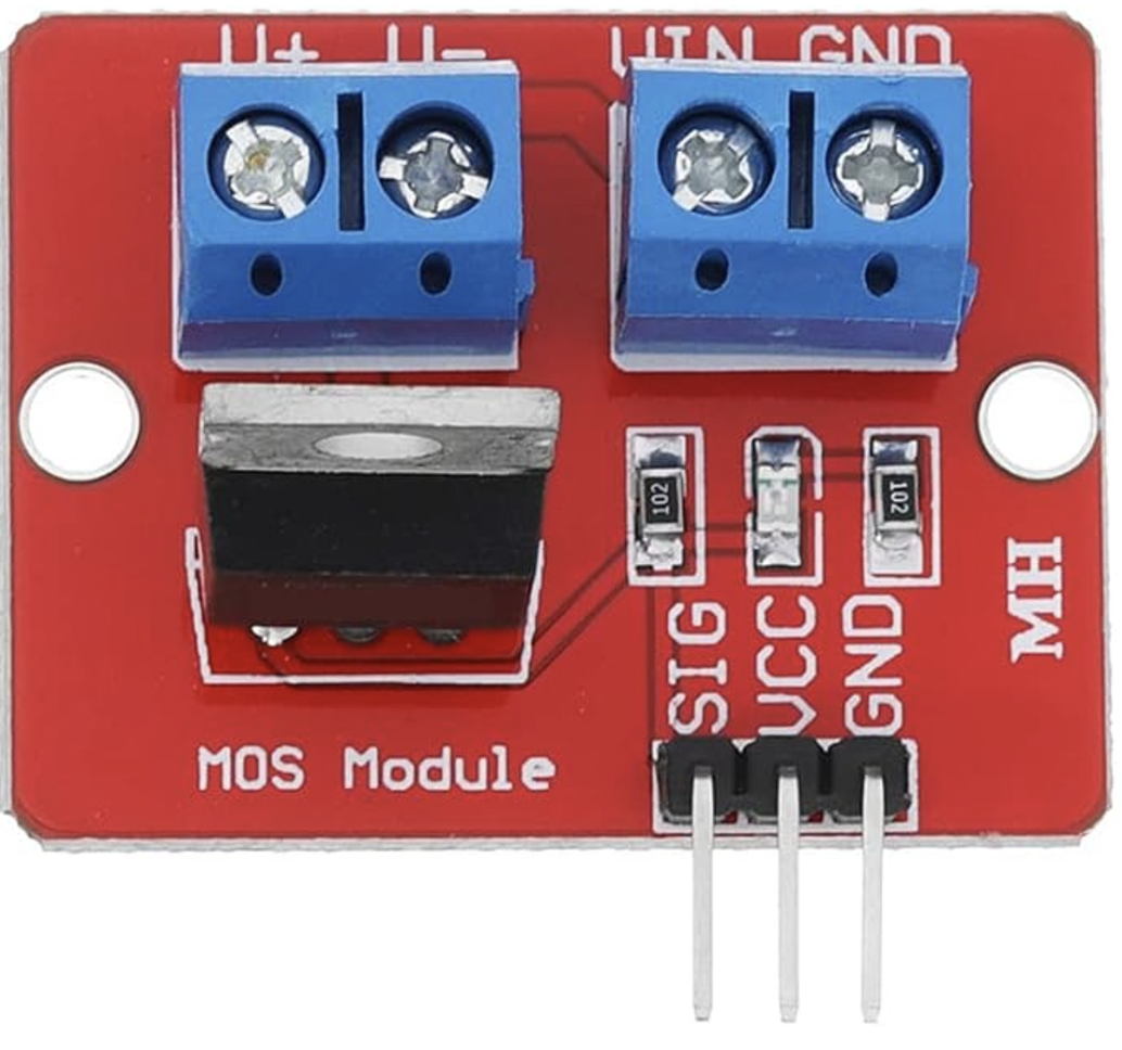
The IRF520 MOSFET Driver Module is a versatile electronic component designed to switch high current loads using a low voltage control signal. This module leverages the IRF520 MOSFET, a type of transistor that can handle significant power levels, making it ideal for various applications. Commonly used in Arduino and other microcontroller projects, the IRF520 MOSFET Driver Module is perfect for controlling motors, LEDs, and other high-power devices.

Explore Projects Built with IRF520 MOSFET Driver Module

Use Cirkit Designer to design, explore, and prototype these projects online. Some projects support real-time simulation. Click "Open Project" to start designing instantly!
Pixhawk-Controlled Solenoid Driver with Voltage Regulation
Image of solenoid control circuit: A project utilizing IRF520 MOSFET Driver Module in a practical application
This circuit uses an LM393 comparator to drive an IRFZ44N MOSFET based on the comparison between two input signals from a pixhawk 2.4.8 flight controller. The MOSFET switches a solenoid, with a diode for back EMF protection, and the system is powered by a Lipo battery with voltage regulation provided by a step-up boost converter and a step-down voltage regulator to ensure stable operation. A resistor is connected to the gate of the MOSFET for proper biasing.
Cirkit Designer LogoOpen Project in Cirkit Designer
Battery-Powered LM393-Based Voltage Comparator Circuit with MOSFET Control
Image of cut off charger: A project utilizing IRF520 MOSFET Driver Module in a practical application
This circuit is a power regulation and control system that uses an LM393 comparator to monitor voltage levels and control a MOSFET (IRFZ44N) for switching. It is powered by a 12V battery and a USB power source, and includes various resistors and capacitors for filtering and stabilization.
Cirkit Designer LogoOpen Project in Cirkit Designer
ESP8266-Controlled Wireless EV Charging System with RFID Authentication
Image of Minor Project: A project utilizing IRF520 MOSFET Driver Module in a practical application
This circuit appears to be a wireless charging system with RFID access control, powered by an AC supply that is rectified and regulated. It includes an ESP8266 microcontroller for managing the charging process and displaying status information on an OLED display. The RFID-RC522 module is used to authorize the charging process, and a MOSFET is likely used to control the power to the charging coil.
Cirkit Designer LogoOpen Project in Cirkit Designer
Dual Motor Control Circuit with LED Indicator and Adjustable Speed
Image of Simple Drone: A project utilizing IRF520 MOSFET Driver Module in a practical application
This circuit is designed to control the speed and direction of coreless motors using MOSFETs, with a potentiometer providing adjustable speed control for one direction. A rocker switch enables power control, and a red LED serves as a power indicator. Diodes are included for motor back-EMF protection.
Cirkit Designer LogoOpen Project in Cirkit Designer

Explore Projects Built with IRF520 MOSFET Driver Module

Use Cirkit Designer to design, explore, and prototype these projects online. Some projects support real-time simulation. Click "Open Project" to start designing instantly!
Image of solenoid control circuit: A project utilizing IRF520 MOSFET Driver Module in a practical application
Pixhawk-Controlled Solenoid Driver with Voltage Regulation
This circuit uses an LM393 comparator to drive an IRFZ44N MOSFET based on the comparison between two input signals from a pixhawk 2.4.8 flight controller. The MOSFET switches a solenoid, with a diode for back EMF protection, and the system is powered by a Lipo battery with voltage regulation provided by a step-up boost converter and a step-down voltage regulator to ensure stable operation. A resistor is connected to the gate of the MOSFET for proper biasing.
Cirkit Designer LogoOpen Project in Cirkit Designer
Image of cut off charger: A project utilizing IRF520 MOSFET Driver Module in a practical application
Battery-Powered LM393-Based Voltage Comparator Circuit with MOSFET Control
This circuit is a power regulation and control system that uses an LM393 comparator to monitor voltage levels and control a MOSFET (IRFZ44N) for switching. It is powered by a 12V battery and a USB power source, and includes various resistors and capacitors for filtering and stabilization.
Cirkit Designer LogoOpen Project in Cirkit Designer
Image of Minor Project: A project utilizing IRF520 MOSFET Driver Module in a practical application
ESP8266-Controlled Wireless EV Charging System with RFID Authentication
This circuit appears to be a wireless charging system with RFID access control, powered by an AC supply that is rectified and regulated. It includes an ESP8266 microcontroller for managing the charging process and displaying status information on an OLED display. The RFID-RC522 module is used to authorize the charging process, and a MOSFET is likely used to control the power to the charging coil.
Cirkit Designer LogoOpen Project in Cirkit Designer
Image of Simple Drone: A project utilizing IRF520 MOSFET Driver Module in a practical application
Dual Motor Control Circuit with LED Indicator and Adjustable Speed
This circuit is designed to control the speed and direction of coreless motors using MOSFETs, with a potentiometer providing adjustable speed control for one direction. A rocker switch enables power control, and a red LED serves as a power indicator. Diodes are included for motor back-EMF protection.
Cirkit Designer LogoOpen Project in Cirkit Designer

Technical Specifications

Key Technical Details

Parameter Value
MOSFET Type N-Channel
Control Voltage 3.3V - 5V
Load Voltage 0V - 24V
Load Current Up to 5A
Power Dissipation 40W
Rds(on) 0.27Ω
Gate Threshold Voltage 2.0V - 4.0V
Operating Temperature -55°C to 175°C

Pin Configuration and Descriptions

Pin Number Pin Name Description
1 VCC Power supply for the module (3.3V - 5V)
2 GND Ground
3 SIG Control signal input (from microcontroller)
4 V+ Load power supply (0V - 24V)
5 V- Load ground

Usage Instructions

How to Use the Component in a Circuit

  1. Power Supply Connection:

    • Connect the VCC pin to the 3.3V or 5V power supply of your microcontroller.
    • Connect the GND pin to the ground of your microcontroller.
  2. Control Signal Connection:

    • Connect the SIG pin to a digital output pin on your microcontroller. This pin will control the MOSFET.
  3. Load Connection:

    • Connect the positive terminal of your load to the V+ pin.
    • Connect the negative terminal of your load to the V- pin.

Important Considerations and Best Practices

  • Ensure that the load current does not exceed the maximum rating of 5A to prevent damage to the MOSFET.
  • Use a heat sink if you are switching high currents to dissipate heat effectively.
  • Keep the control signal voltage within the specified range (3.3V - 5V) to ensure proper operation.
  • Verify all connections before powering up the circuit to avoid short circuits or incorrect wiring.

Example: Connecting to an Arduino UNO

// Define the pin connected to the SIG pin of the IRF520 module
const int controlPin = 9;

void setup() {
  // Set the control pin as an output
  pinMode(controlPin, OUTPUT);
}

void loop() {
  // Turn the load on
  digitalWrite(controlPin, HIGH);
  delay(1000); // Keep the load on for 1 second

  // Turn the load off
  digitalWrite(controlPin, LOW);
  delay(1000); // Keep the load off for 1 second
}

Troubleshooting and FAQs

Common Issues and Solutions

  1. Load Not Turning On:

    • Check Connections: Ensure all connections are secure and correct.
    • Verify Control Signal: Make sure the control signal from the microcontroller is within the specified range (3.3V - 5V).
    • Inspect Load: Confirm that the load is functional and not damaged.
  2. MOSFET Overheating:

    • Current Rating: Ensure the load current does not exceed 5A.
    • Use a Heat Sink: Attach a heat sink to the MOSFET to help dissipate heat.
  3. Inconsistent Operation:

    • Power Supply Stability: Ensure the power supply is stable and within the specified voltage range.
    • Signal Integrity: Check for noise or interference on the control signal line.

FAQs

Q1: Can I use the IRF520 MOSFET Driver Module with a 3.3V microcontroller?

  • Yes, the module is compatible with both 3.3V and 5V control signals.

Q2: What is the maximum voltage I can switch with this module?

  • The module can switch loads with a voltage up to 24V.

Q3: Do I need a heat sink for the MOSFET?

  • A heat sink is recommended if you are switching high currents to prevent overheating.

Q4: Can I use this module to control an AC load?

  • No, the IRF520 MOSFET Driver Module is designed for DC loads only.

By following this documentation, users can effectively integrate the IRF520 MOSFET Driver Module into their projects, ensuring reliable and efficient operation.