How to Use Connector: Examples, Pinouts, and Specs
Introduction
A connector is a device used to join electrical circuits, enabling the transfer of signals or power between different components. Connectors are essential in electronic systems, providing a reliable and often detachable interface between various parts of a circuit. They come in various shapes, sizes, and configurations to suit different applications.
Common applications and use cases include:
- Connecting power supplies to devices.
- Linking sensors, actuators, or modules to microcontrollers.
- Establishing communication between electronic boards or systems.
- Providing modularity in electronic designs for easy assembly and maintenance.
Explore Projects Built with Connector


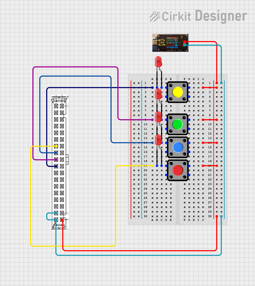
Explore Projects Built with Connector
Technical Specifications
Connectors vary widely in their specifications depending on the type and application. Below are general technical details and an example pin configuration for a common 4-pin connector:
General Specifications
- Voltage Rating: Typically 12V to 250V (varies by type).
- Current Rating: 1A to 30A (depending on the connector size and type).
- Contact Resistance: < 20 mΩ.
- Insulation Resistance: > 1000 MΩ.
- Operating Temperature: -40°C to +105°C.
- Durability: 500 to 10,000 mating cycles (depending on the material and design).
Example Pin Configuration (4-Pin Connector)
| Pin Number | Name | Description |
|---|---|---|
| 1 | VCC (Power) | Supplies power to the connected device. |
| 2 | GND (Ground) | Provides the ground connection. |
| 3 | Signal/Data+ | Transmits positive signal or data line. |
| 4 | Signal/Data- | Transmits negative signal or data line. |
Usage Instructions
How to Use the Connector in a Circuit
- Identify the Connector Type: Determine the type of connector (e.g., male, female, header, socket) and ensure it matches the mating part.
- Check Pinout: Refer to the datasheet or pin configuration to correctly identify each pin's function.
- Solder or Crimp Wires: For permanent connections, solder wires to the connector pins. For detachable connections, use crimp terminals or pre-assembled connectors.
- Secure the Connection: Ensure the connector is firmly mated to its counterpart to avoid loose connections.
- Test the Circuit: Verify continuity and proper signal/power transfer after connecting.
Important Considerations and Best Practices
- Match Ratings: Ensure the connector's voltage and current ratings meet or exceed the circuit requirements.
- Avoid Overheating: Do not exceed the connector's current rating to prevent overheating or damage.
- Use Proper Tools: Use appropriate crimping tools or soldering equipment for reliable connections.
- Protect Against Moisture: For outdoor or harsh environments, use waterproof connectors or apply heat-shrink tubing for added protection.
- Label Connections: Clearly label wires and connectors to avoid confusion during assembly or maintenance.
Example: Connecting a Sensor to an Arduino UNO
Below is an example of using a 4-pin connector to connect a temperature sensor to an Arduino UNO:
Circuit Diagram
- Pin 1 (VCC): Connect to Arduino 5V.
- Pin 2 (GND): Connect to Arduino GND.
- Pin 3 (Signal/Data+): Connect to Arduino digital pin 2.
- Pin 4 (Signal/Data-): Not used in this example.
Arduino Code
// Example code to read data from a temperature sensor connected via a 4-pin connector
const int sensorPin = 2; // Pin connected to Signal/Data+ of the sensor

void setup() {
  Serial.begin(9600); // Initialize serial communication
  pinMode(sensorPin, INPUT); // Set sensor pin as input
}

void loop() {
  int sensorValue = digitalRead(sensorPin); // Read sensor data
  Serial.print("Sensor Value: ");
  Serial.println(sensorValue); // Print the sensor value to the Serial Monitor
  delay(1000); // Wait for 1 second before reading again
}
Troubleshooting and FAQs
Common Issues and Solutions
Loose Connections:
- Issue: The circuit intermittently loses power or signal.
- Solution: Ensure the connector is fully seated and locked in place. Check for damaged pins or contacts.
Incorrect Pinout:
- Issue: The device does not function as expected.
- Solution: Double-check the pin configuration and wiring. Refer to the datasheet for correct pin assignments.
Overheating:
- Issue: The connector becomes hot during operation.
- Solution: Verify that the current does not exceed the connector's rating. Use a connector with a higher current capacity if needed.
Corrosion or Dirt:
- Issue: Poor contact due to corrosion or debris on the pins.
- Solution: Clean the connector pins with isopropyl alcohol and a soft brush. Use connectors with gold-plated contacts for better corrosion resistance.
FAQs
Q: Can I use a connector rated for 12V in a 24V circuit?
- A: No, always use a connector rated for the voltage and current of your circuit to ensure safety and reliability.
Q: How do I prevent accidental disconnections?
- A: Use locking connectors or secure the connection with cable ties or clamps.
Q: Are all connectors waterproof?
- A: No, only connectors specifically designed for waterproof applications (e.g., IP67-rated) can withstand moisture. Use appropriate connectors for outdoor or wet environments.
By following these guidelines, you can effectively use connectors in your electronic projects and ensure reliable performance.