How to Use Electrically Isolated EZO™ Carrier Board: Examples, Pinouts, and Specs
Introduction
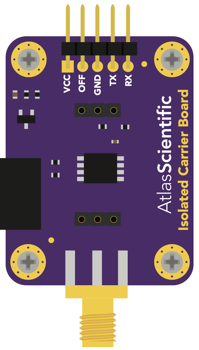
The Electrically Isolated EZO™ Carrier Board, manufactured by Atlas Scientific, is a specialized circuit board designed to interface seamlessly with EZO™ electrochemical sensors. This carrier board provides electrical isolation, which is critical for preventing noise and interference in sensor readings. By isolating the sensor from the rest of the circuit, it ensures highly accurate and reliable measurements, even in electrically noisy environments.
Explore Projects Built with Electrically Isolated EZO™ Carrier Board


Explore Projects Built with Electrically Isolated EZO™ Carrier Board
Common Applications and Use Cases
- pH, ORP, dissolved oxygen, and conductivity measurements in industrial and laboratory settings.
- Water quality monitoring in aquariums, hydroponics, and environmental research.
- Applications requiring precise electrochemical sensor readings in electrically noisy environments.
- Integration of EZO™ sensors with microcontrollers like Arduino, Raspberry Pi, or other embedded systems.
Technical Specifications
Key Technical Details
- Input Voltage: 3.3V to 5V DC
- Output Voltage: 3.3V or 5V DC (selectable via jumper)
- Electrical Isolation: 2500V RMS
- Communication Protocols Supported: UART and I2C
- Dimensions: 25.4mm x 25.4mm (1" x 1")
- Operating Temperature Range: -40°C to 85°C
- Mounting: Standard 4-hole mounting for easy integration
Pin Configuration and Descriptions
The Electrically Isolated EZO™ Carrier Board features two sets of pins: one for the microcontroller side and one for the sensor side. Below is the pin configuration:
Microcontroller Side
| Pin Name | Description |
|---|---|
| VCC | Power input (3.3V to 5V DC) |
| GND | Ground connection |
| TX | UART transmit pin (connects to RX of the microcontroller) |
| RX | UART receive pin (connects to TX of the microcontroller) |
| SCL | I2C clock line (connects to SCL of the microcontroller) |
| SDA | I2C data line (connects to SDA of the microcontroller) |
Sensor Side
| Pin Name | Description |
|---|---|
| VCC | Power output to the EZO™ sensor (3.3V or 5V, selectable via jumper) |
| GND | Ground connection |
| TX | UART transmit pin (connects to RX of the EZO™ sensor) |
| RX | UART receive pin (connects to TX of the EZO™ sensor) |
| SCL | I2C clock line (connects to SCL of the EZO™ sensor) |
| SDA | I2C data line (connects to SDA of the EZO™ sensor) |
Usage Instructions
How to Use the Component in a Circuit
Powering the Board:
- Connect the VCC pin on the microcontroller side to a 3.3V or 5V power source.
- Connect the GND pin on the microcontroller side to the ground of your circuit.
Connecting the Microcontroller:
- For UART communication, connect the TX and RX pins of the carrier board to the RX and TX pins of your microcontroller, respectively.
- For I2C communication, connect the SCL and SDA pins of the carrier board to the corresponding SCL and SDA pins of your microcontroller.
Connecting the EZO™ Sensor:
- Use the sensor side pins to connect the EZO™ sensor. Ensure the TX, RX, SCL, and SDA pins are correctly matched.
- Set the jumper on the carrier board to select the appropriate output voltage (3.3V or 5V) for your EZO™ sensor.
Communication Protocol:
- Configure your microcontroller to use either UART or I2C communication, depending on your application.
Mounting:
- Secure the carrier board using the four mounting holes to ensure stability in your setup.
Important Considerations and Best Practices
- Always ensure the jumper is set to the correct voltage (3.3V or 5V) before connecting the EZO™ sensor to avoid damage.
- Use short, high-quality wires to minimize noise and maintain signal integrity.
- If using I2C, ensure that the pull-up resistors are properly configured in your circuit.
- Avoid placing the carrier board near high-frequency or high-power components to reduce the risk of interference.
Example Code for Arduino UNO
Below is an example of how to interface the Electrically Isolated EZO™ Carrier Board with an EZO™ pH sensor using UART communication:
#include <SoftwareSerial.h>

// Define the RX and TX pins for SoftwareSerial
#define RX_PIN 10  // Connect to TX of the carrier board
#define TX_PIN 11  // Connect to RX of the carrier board

SoftwareSerial ezoSerial(RX_PIN, TX_PIN);

void setup() {
  Serial.begin(9600);          // Start the serial monitor
  ezoSerial.begin(9600);       // Start communication with the EZO™ sensor
  Serial.println("EZO™ Carrier Board Example");
}

void loop() {
  // Send a command to the EZO™ sensor
  ezoSerial.println("R");      // "R" command requests a reading from the sensor
  delay(1000);                 // Wait for the sensor to process the command

  // Check if data is available from the sensor
  if (ezoSerial.available()) {
    String sensorData = "";
    while (ezoSerial.available()) {
      char c = ezoSerial.read();
      sensorData += c;
    }
    Serial.println("Sensor Reading: " + sensorData);
  }
}
Troubleshooting and FAQs
Common Issues and Solutions
No Data from the Sensor:
- Cause: Incorrect wiring or communication protocol mismatch.
- Solution: Double-check all connections and ensure the microcontroller and sensor are configured for the same protocol (UART or I2C).
Inaccurate Readings:
- Cause: Electrical noise or incorrect voltage selection.
- Solution: Ensure the jumper is set to the correct voltage for the sensor. Minimize noise by using short wires and keeping the carrier board away from high-frequency components.
Sensor Not Responding:
- Cause: Sensor not powered or damaged.
- Solution: Verify that the sensor is receiving power from the carrier board. Check the VCC and GND connections.
I2C Communication Issues:
- Cause: Missing or incorrect pull-up resistors.
- Solution: Add appropriate pull-up resistors (typically 4.7kΩ) to the SDA and SCL lines.
FAQs
Can I use multiple EZO™ sensors with one carrier board?
- No, each EZO™ sensor requires its own Electrically Isolated EZO™ Carrier Board for proper isolation.
What is the purpose of electrical isolation?
- Electrical isolation prevents noise and interference from affecting the sensor readings, ensuring accurate measurements.
Can I use this board with a 3.3V microcontroller?
- Yes, the carrier board supports both 3.3V and 5V microcontrollers. Ensure the jumper is set correctly for the sensor voltage.
Is the carrier board compatible with all EZO™ sensors?
- Yes, the carrier board is designed to work with all Atlas Scientific EZO™ sensors.