Cirkit Designer Logo
Cirkit Designer
Your all-in-one circuit design IDE
Home / 
Component Documentation

How to Use Adafruit 12mm Coin Cell Breakout: Examples, Pinouts, and Specs

Image of Adafruit 12mm Coin Cell Breakout
Cirkit Designer LogoDesign with Adafruit 12mm Coin Cell Breakout in Cirkit Designer

Introduction

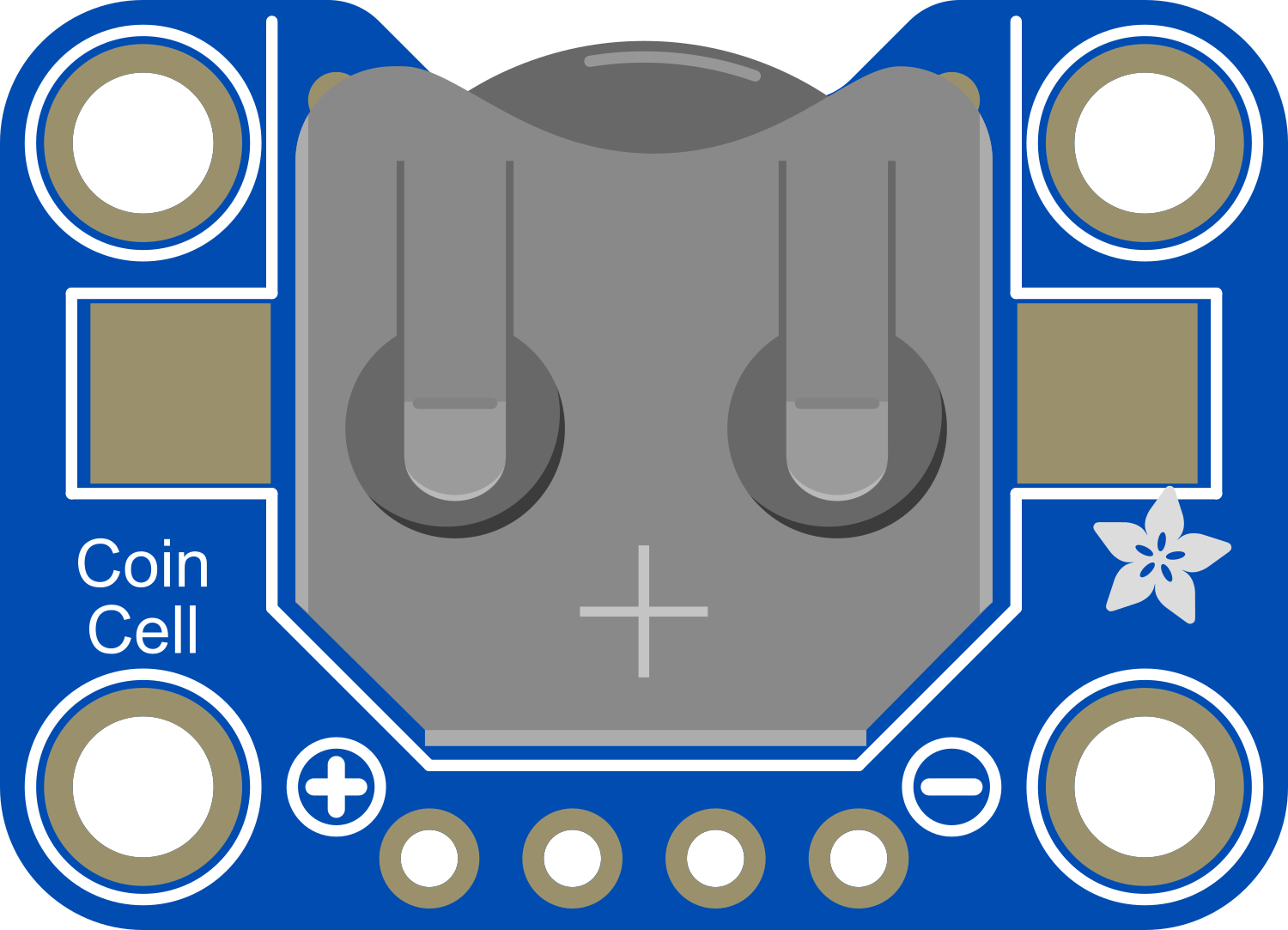
The Adafruit 12mm Coin Cell Breakout is a compact and convenient solution for powering small, low-power electronic projects. This breakout board is specifically designed to hold a 12mm coin cell battery, such as the CR1220. It includes an integrated battery holder, an on-board power switch, and an LED that serves as a power indicator. This component is ideal for wearable electronics, portable devices, and any application where a compact, on-the-go power source is required.

Explore Projects Built with Adafruit 12mm Coin Cell Breakout

Use Cirkit Designer to design, explore, and prototype these projects online. Some projects support real-time simulation. Click "Open Project" to start designing instantly!
Biometric and RFID Security System with Dual Adafruit Feather nRF52840 Controllers
Image of Rfid access control: A project utilizing Adafruit 12mm Coin Cell Breakout in a practical application
This circuit features two Adafruit Feather nRF52840 microcontrollers, each interfaced with an RFID-RC522 module for RFID communication and an AT24C256 external EEPROM for additional memory storage. One of the microcontrollers is also connected to an R307 Fingerprint Sensor for biometric input, and both microcontrollers are powered by a shared power supply and a coin cell breakout for backup or RTC power. The circuit is likely designed for secure access control or identification purposes, utilizing both RFID and fingerprint authentication, with data storage capabilities.
Cirkit Designer LogoOpen Project in Cirkit Designer
Battery-Powered Sensor Hub with Adafruit QT Py RP2040 and OLED Display
Image of 512: A project utilizing Adafruit 12mm Coin Cell Breakout in a practical application
This circuit features an Adafruit QT Py RP2040 microcontroller interfacing with an MPU-6050 accelerometer, an Adafruit APDS-9960 sensor, and a 0.96" OLED display via I2C communication. It is powered by a 3.7V LiPo battery and includes a green LED with a current-limiting resistor connected to an analog pin of the microcontroller.
Cirkit Designer LogoOpen Project in Cirkit Designer
Battery-Powered Smart Light with Proximity Sensor and OLED Display using Adafruit QT Py RP2040
Image of lab: A project utilizing Adafruit 12mm Coin Cell Breakout in a practical application
This circuit is a portable, battery-powered system featuring an Adafruit QT Py RP2040 microcontroller that interfaces with an OLED display, a proximity sensor, an accelerometer, and an RGB LED strip. The system is powered by a lithium-ion battery with a step-up boost converter to provide 5V for the LED strip, and it includes a toggle switch for power control. The microcontroller communicates with the sensors and display via I2C.
Cirkit Designer LogoOpen Project in Cirkit Designer
Battery-Powered Smart Sensor Hub with Adafruit QT Py RP2040
Image of wearable final: A project utilizing Adafruit 12mm Coin Cell Breakout in a practical application
This circuit features an Adafruit QT Py RP2040 microcontroller interfaced with an APDS9960 proximity sensor, an MPU6050 accelerometer and gyroscope, and an OLED display via I2C communication. It also includes a buzzer controlled by the microcontroller and is powered by a 3.7V LiPo battery with a toggle switch for power control.
Cirkit Designer LogoOpen Project in Cirkit Designer

Explore Projects Built with Adafruit 12mm Coin Cell Breakout

Use Cirkit Designer to design, explore, and prototype these projects online. Some projects support real-time simulation. Click "Open Project" to start designing instantly!
Image of Rfid access control: A project utilizing Adafruit 12mm Coin Cell Breakout in a practical application
Biometric and RFID Security System with Dual Adafruit Feather nRF52840 Controllers
This circuit features two Adafruit Feather nRF52840 microcontrollers, each interfaced with an RFID-RC522 module for RFID communication and an AT24C256 external EEPROM for additional memory storage. One of the microcontrollers is also connected to an R307 Fingerprint Sensor for biometric input, and both microcontrollers are powered by a shared power supply and a coin cell breakout for backup or RTC power. The circuit is likely designed for secure access control or identification purposes, utilizing both RFID and fingerprint authentication, with data storage capabilities.
Cirkit Designer LogoOpen Project in Cirkit Designer
Image of 512: A project utilizing Adafruit 12mm Coin Cell Breakout in a practical application
Battery-Powered Sensor Hub with Adafruit QT Py RP2040 and OLED Display
This circuit features an Adafruit QT Py RP2040 microcontroller interfacing with an MPU-6050 accelerometer, an Adafruit APDS-9960 sensor, and a 0.96" OLED display via I2C communication. It is powered by a 3.7V LiPo battery and includes a green LED with a current-limiting resistor connected to an analog pin of the microcontroller.
Cirkit Designer LogoOpen Project in Cirkit Designer
Image of lab: A project utilizing Adafruit 12mm Coin Cell Breakout in a practical application
Battery-Powered Smart Light with Proximity Sensor and OLED Display using Adafruit QT Py RP2040
This circuit is a portable, battery-powered system featuring an Adafruit QT Py RP2040 microcontroller that interfaces with an OLED display, a proximity sensor, an accelerometer, and an RGB LED strip. The system is powered by a lithium-ion battery with a step-up boost converter to provide 5V for the LED strip, and it includes a toggle switch for power control. The microcontroller communicates with the sensors and display via I2C.
Cirkit Designer LogoOpen Project in Cirkit Designer
Image of wearable final: A project utilizing Adafruit 12mm Coin Cell Breakout in a practical application
Battery-Powered Smart Sensor Hub with Adafruit QT Py RP2040
This circuit features an Adafruit QT Py RP2040 microcontroller interfaced with an APDS9960 proximity sensor, an MPU6050 accelerometer and gyroscope, and an OLED display via I2C communication. It also includes a buzzer controlled by the microcontroller and is powered by a 3.7V LiPo battery with a toggle switch for power control.
Cirkit Designer LogoOpen Project in Cirkit Designer

Common Applications and Use Cases

  • Wearable electronics (e.g., LED badges, smart jewelry)
  • Small gadgets and toys
  • Portable prototypes
  • Real-time clocks or backup power for memory chips
  • Event or conference badges

Technical Specifications

Key Technical Details

  • Battery Compatibility: 12mm coin cell, CR1220 or equivalent
  • Voltage: Typically 3V (depending on the battery used)
  • Current: Dependent on the connected load and battery capacity
  • Power Ratings: Dependent on the battery's specifications
  • Dimensions: Small footprint to fit in tight spaces

Pin Configuration and Descriptions

Pin Name Description
+ Positive terminal connected to the battery
- Negative terminal connected to the battery
S1 Slide switch to control power
LED Power indicator LED

Usage Instructions

How to Use the Component in a Circuit

  1. Inserting the Battery:

    • Open the battery holder and carefully insert a 12mm coin cell battery, ensuring the positive side is facing up.
  2. Connecting to a Circuit:

    • Connect the '+' pin to the positive power rail of your circuit.
    • Connect the '-' pin to the ground (GND) of your circuit.
  3. Powering the Circuit:

    • Slide the switch to the 'ON' position to power the circuit.
    • The onboard LED should light up, indicating that power is being supplied.

Important Considerations and Best Practices

  • Battery Orientation: Ensure the battery is inserted correctly to prevent damage to the breakout board or the battery.
  • Power Consumption: Be mindful of the power consumption of your circuit, as coin cell batteries have limited capacity.
  • Switch Handling: Use the slide switch gently to avoid breaking it.
  • LED Indicator: The LED is a useful tool to quickly check if the circuit is powered, but it also consumes power. In ultra-low-power designs, consider disabling the LED if necessary.

Troubleshooting and FAQs

Common Issues

  • LED Not Lighting Up:

    • Check if the battery is inserted correctly with the correct orientation.
    • Ensure the slide switch is in the 'ON' position.
    • Verify that the battery is not depleted.
  • Insufficient Power to Circuit:

    • Confirm that the connected load does not exceed the battery's capacity.
    • Check for any short circuits or incorrect connections in your circuit.

Solutions and Tips for Troubleshooting

  • If the LED does not light up, try replacing the battery with a new one.
  • For power issues, calculate the expected battery life based on the current draw of your circuit and compare it with the actual performance.
  • Inspect the breakout board for any physical damage or loose connections.

FAQs

Q: Can I use a battery other than the CR1220? A: The holder is designed for 12mm coin cells, so other batteries with the same dimensions and voltage should work.

Q: How long will the battery last? A: Battery life depends on the capacity of the coin cell and the current draw of your circuit. Check the battery's datasheet for capacity information.

Q: Is it possible to recharge the battery using this breakout board? A: No, this breakout board does not include charging circuitry. Use only non-rechargeable coin cell batteries.

Q: Can I disable the power indicator LED? A: Yes, you can desolder the LED or cut the trace leading to it if you need to conserve power.

Example Code for Arduino UNO

// Example code to demonstrate how to control an LED using the Adafruit 12mm Coin Cell Breakout

const int ledPin = 13; // Built-in LED pin on Arduino UNO

void setup() {
  pinMode(ledPin, OUTPUT); // Set the LED pin as an output
}

void loop() {
  digitalWrite(ledPin, HIGH); // Turn on the LED
  delay(1000);                // Wait for 1 second
  digitalWrite(ledPin, LOW);  // Turn off the LED
  delay(1000);                // Wait for 1 second
}

Note: This example assumes that the Adafruit 12mm Coin Cell Breakout is connected to the Arduino UNO's 5V and GND pins, and that the onboard LED is used as an indicator. If you're using an external LED, make sure to include a current-limiting resistor in series with the LED to prevent damage.