Cirkit Designer Logo
Cirkit Designer
Your all-in-one circuit design IDE
Home / 
Component Documentation

How to Use KX134: Examples, Pinouts, and Specs

Image of KX134
Cirkit Designer LogoDesign with KX134 in Cirkit Designer

Introduction

The KX134 is a high-performance, low-power 3-axis accelerometer designed by Kionix, a subsidiary of ROHM Semiconductor. This sensor is capable of measuring acceleration with a full-scale range of ±8g, ±16g, ±32g, and ±64g. It is commonly used in applications such as motion detection, vibration monitoring, and dynamic orientation detection in devices like smartphones, gaming controllers, and vehicle navigation systems.

Explore Projects Built with KX134

Use Cirkit Designer to design, explore, and prototype these projects online. Some projects support real-time simulation. Click "Open Project" to start designing instantly!
Wireless Joystick-Controlled Interface with Arduino Nano and NRF24L01
Image of Transmitter 11: A project utilizing KX134 in a practical application
This circuit features an Arduino Nano interfaced with a KY-023 Dual Axis Joystick Module for analog input, and an NRF24L01 module for wireless communication. The joystick provides x and y-axis control signals to the Arduino's analog inputs and a switch signal to a digital input, while the NRF24L01 enables the Arduino to communicate with other devices wirelessly. The 2x 18650 batteries supply power to the Arduino, which in turn powers the joystick and the NRF24L01 module.
Cirkit Designer LogoOpen Project in Cirkit Designer
IR Obstacle Detection System with Relay-Controlled Gearmotors and Boost Converters
Image of LFR 1: A project utilizing KX134 in a practical application
This circuit consists of two FC-51 IR Obstacle Sensors connected to two KF-301 relays, which likely serve as triggers for switching the relays. Four gearmotors are powered through two XL6009E1 Boost Converters, which are likely used to step up the voltage from a 2-cell 18650 Li-ion battery pack. The relays appear to control the power flow to the boost converters, and thus to the gearmotors, based on the obstacle detection inputs.
Cirkit Designer LogoOpen Project in Cirkit Designer
Satellite-Based Timing and Navigation System with SDR and Atomic Clock Synchronization
Image of GPS 시스템 측정 구성도_Confirm: A project utilizing KX134 in a practical application
This circuit appears to be a complex system involving power supply management, GPS and timing synchronization, and data communication. It includes a SI-TEX G1 Satellite Compass for GPS data, an XHTF1021 Atomic Rubidium Clock for precise timing, and Ettus USRP B200 units for software-defined radio communication. Power is supplied through various SMPS units and distributed via terminal blocks and DC jacks. Data communication is facilitated by Beelink MINI S12 N95 computers, RS232 splitters, and a 1000BASE-T Media Converter for network connectivity. RF Directional Couplers are used to interface antennas with the USRP units, and the entire system is likely contained within cases for protection and organization.
Cirkit Designer LogoOpen Project in Cirkit Designer
Battery-Powered Emergency Alert System with NUCLEO-F072RB, SIM800L, and GPS NEO 6M
Image of women safety: A project utilizing KX134 in a practical application
This circuit is an emergency alert system that uses a NUCLEO-F072RB microcontroller to send SMS alerts and make calls via a SIM800L GSM module, while obtaining location data from a GPS NEO 6M module. The system is powered by a Li-ion battery and includes a TP4056 module for battery charging and protection, with a rocker switch to control power to the microcontroller.
Cirkit Designer LogoOpen Project in Cirkit Designer

Explore Projects Built with KX134

Use Cirkit Designer to design, explore, and prototype these projects online. Some projects support real-time simulation. Click "Open Project" to start designing instantly!
Image of Transmitter 11: A project utilizing KX134 in a practical application
Wireless Joystick-Controlled Interface with Arduino Nano and NRF24L01
This circuit features an Arduino Nano interfaced with a KY-023 Dual Axis Joystick Module for analog input, and an NRF24L01 module for wireless communication. The joystick provides x and y-axis control signals to the Arduino's analog inputs and a switch signal to a digital input, while the NRF24L01 enables the Arduino to communicate with other devices wirelessly. The 2x 18650 batteries supply power to the Arduino, which in turn powers the joystick and the NRF24L01 module.
Cirkit Designer LogoOpen Project in Cirkit Designer
Image of LFR 1: A project utilizing KX134 in a practical application
IR Obstacle Detection System with Relay-Controlled Gearmotors and Boost Converters
This circuit consists of two FC-51 IR Obstacle Sensors connected to two KF-301 relays, which likely serve as triggers for switching the relays. Four gearmotors are powered through two XL6009E1 Boost Converters, which are likely used to step up the voltage from a 2-cell 18650 Li-ion battery pack. The relays appear to control the power flow to the boost converters, and thus to the gearmotors, based on the obstacle detection inputs.
Cirkit Designer LogoOpen Project in Cirkit Designer
Image of GPS 시스템 측정 구성도_Confirm: A project utilizing KX134 in a practical application
Satellite-Based Timing and Navigation System with SDR and Atomic Clock Synchronization
This circuit appears to be a complex system involving power supply management, GPS and timing synchronization, and data communication. It includes a SI-TEX G1 Satellite Compass for GPS data, an XHTF1021 Atomic Rubidium Clock for precise timing, and Ettus USRP B200 units for software-defined radio communication. Power is supplied through various SMPS units and distributed via terminal blocks and DC jacks. Data communication is facilitated by Beelink MINI S12 N95 computers, RS232 splitters, and a 1000BASE-T Media Converter for network connectivity. RF Directional Couplers are used to interface antennas with the USRP units, and the entire system is likely contained within cases for protection and organization.
Cirkit Designer LogoOpen Project in Cirkit Designer
Image of women safety: A project utilizing KX134 in a practical application
Battery-Powered Emergency Alert System with NUCLEO-F072RB, SIM800L, and GPS NEO 6M
This circuit is an emergency alert system that uses a NUCLEO-F072RB microcontroller to send SMS alerts and make calls via a SIM800L GSM module, while obtaining location data from a GPS NEO 6M module. The system is powered by a Li-ion battery and includes a TP4056 module for battery charging and protection, with a rocker switch to control power to the microcontroller.
Cirkit Designer LogoOpen Project in Cirkit Designer

Technical Specifications

Key Features

  • Sensing Range: ±8g, ±16g, ±32g, ±64g (selectable)
  • Output: Digital (I2C/SPI)
  • Voltage Supply: 1.7V to 3.6V
  • Current Consumption: 0.9µA (standby), 145µA (operating at low power)
  • Interface: I2C (up to 3.4MHz), SPI (up to 10MHz)
  • Operating Temperature: -40°C to +85°C

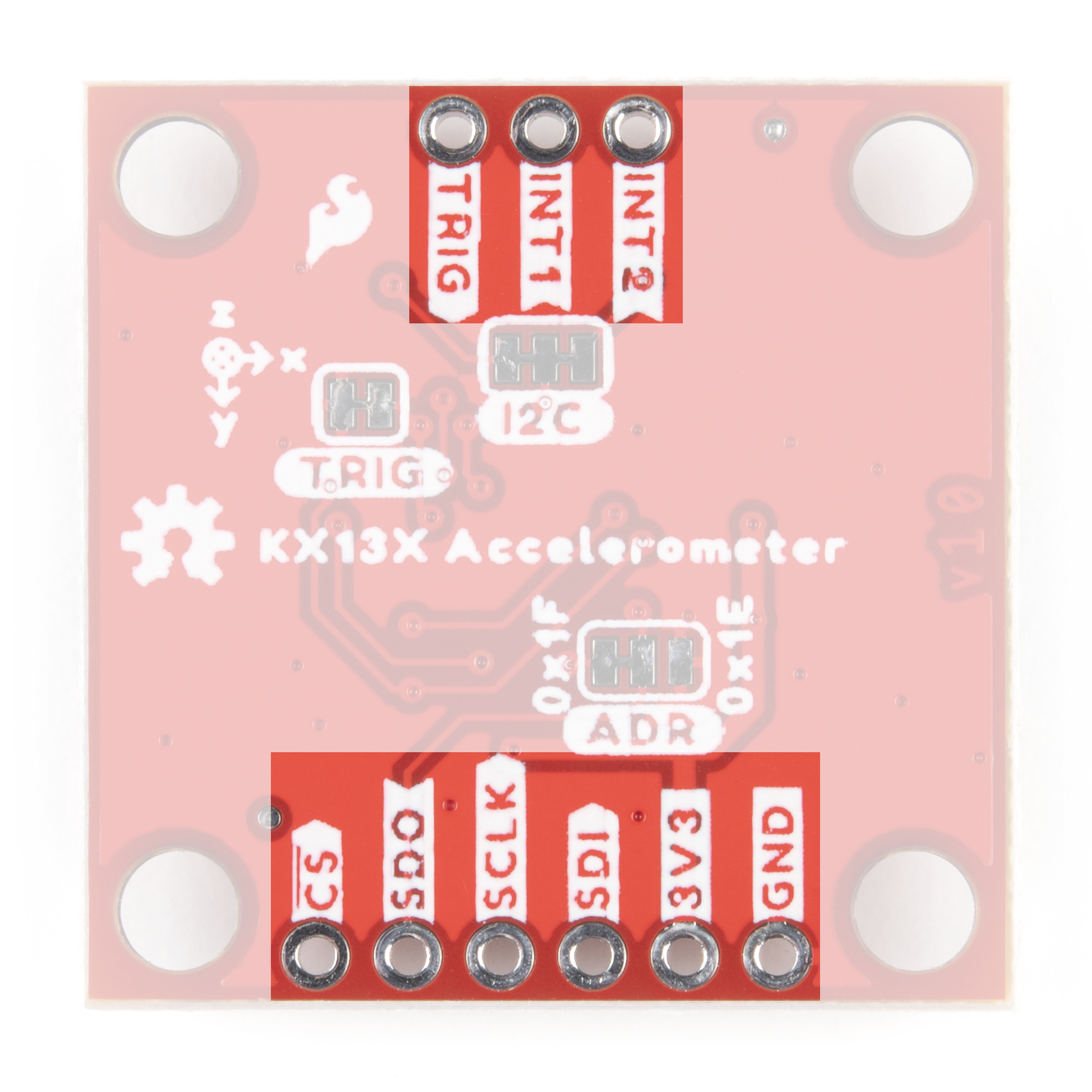
Pin Configuration and Descriptions

Pin Number Pin Name Description
1 VDD Power supply voltage
2 GND Ground
3 SCL/SPC Serial Clock for I2C/SPI Clock
4 SDA/SDI Serial Data for I2C/SPI Data Input
5 SDO SPI Data Output (optional)
6 CS Chip Select for SPI (active low)
7 INT1 Interrupt 1 (configurable)
8 INT2 Interrupt 2 (configurable)

Usage Instructions

Integration into a Circuit

  1. Power Supply: Connect VDD to a 1.7V to 3.6V source and GND to the system ground.
  2. Data Interface: For I2C communication, connect SCL to the I2C clock line and SDA to the I2C data line. For SPI, connect SCL/SPC to the SPI clock, SDA/SDI to the SPI data input, and SDO to the SPI data output if needed.
  3. Chip Select: For SPI, the CS pin must be connected to a digital output pin on the microcontroller and driven low to initiate communication.
  4. Interrupts: INT1 and INT2 can be connected to digital input pins on the microcontroller if interrupt-driven operation is required.

Best Practices

  • Ensure that the power supply is stable and within the specified voltage range.
  • Use pull-up resistors on the I2C lines if they are not already provided in the microcontroller.
  • Keep the communication lines as short as possible to reduce noise and interference.
  • Configure the sensor settings such as range and bandwidth according to the application requirements.

Example Code for Arduino UNO

#include <Wire.h>

// KX134 I2C address (assuming SDO pin is connected to GND)
const int KX134_I2C_ADDRESS = 0x1E;

void setup() {
  Wire.begin(); // Initialize I2C
  Serial.begin(9600); // Start serial communication at 9600 baud rate

  // Setup KX134 (write appropriate configuration registers)
  // This is a placeholder for actual configuration code
}

void loop() {
  // Read acceleration data from KX134
  // This is a placeholder for actual data reading code

  // Process and output the acceleration data
  // This is a placeholder for actual data processing and output
}

Note: The above code is a template and does not include specific register addresses or data processing. Users must refer to the KX134 datasheet for detailed register descriptions and configure the device accordingly.

Troubleshooting and FAQs

Common Issues

  • No Data Output: Ensure that the power supply is within range and that the I2C/SPI lines are correctly connected.
  • Inaccurate Readings: Verify that the accelerometer range is correctly set for your application. Also, check for any sources of electromagnetic interference.

Solutions and Tips

  • Power Supply Issues: Use a decoupling capacitor close to the VDD pin to filter out noise.
  • Communication Errors: Check for proper pull-up resistors on the I2C lines and ensure that the SPI lines are not too long or susceptible to crosstalk.

FAQs

Q: Can the KX134 operate in both I2C and SPI modes? A: Yes, the KX134 can operate in either I2C or SPI mode, but the mode must be selected correctly through the pin connections and configuration settings.

Q: What is the purpose of the INT1 and INT2 pins? A: These pins can be configured to output interrupt signals for various events such as motion detection, free-fall, or data ready notifications.

Q: How do I change the sensing range of the KX134? A: The sensing range can be changed by writing to the appropriate configuration registers. Refer to the datasheet for the specific register settings.

Q: Is the KX134 suitable for battery-powered applications? A: Yes, with its low-power consumption in standby and operating modes, the KX134 is suitable for battery-powered applications.

For more detailed information, please refer to the KX134 datasheet provided by Kionix.