How to Use EMC2101 Fan/PWM Controller: Examples, Pinouts, and Specs
Introduction
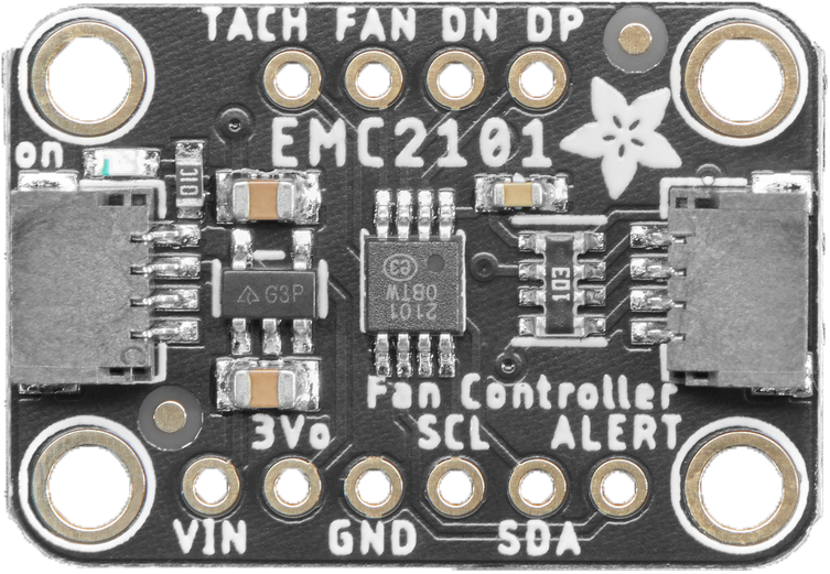
The EMC2101 Fan/PWM Controller is an advanced, programmable fan controller designed for managing the speed of a brushless DC fan using Pulse Width Modulation (PWM). Manufactured by Adafruit (part ID: 4808), this component is ideal for thermal management within electronic systems. Common applications include computer CPU cooling, power supply units, LED lighting systems, and any other scenario where precise fan speed control is required to maintain an optimal temperature.
Explore Projects Built with EMC2101 Fan/PWM Controller
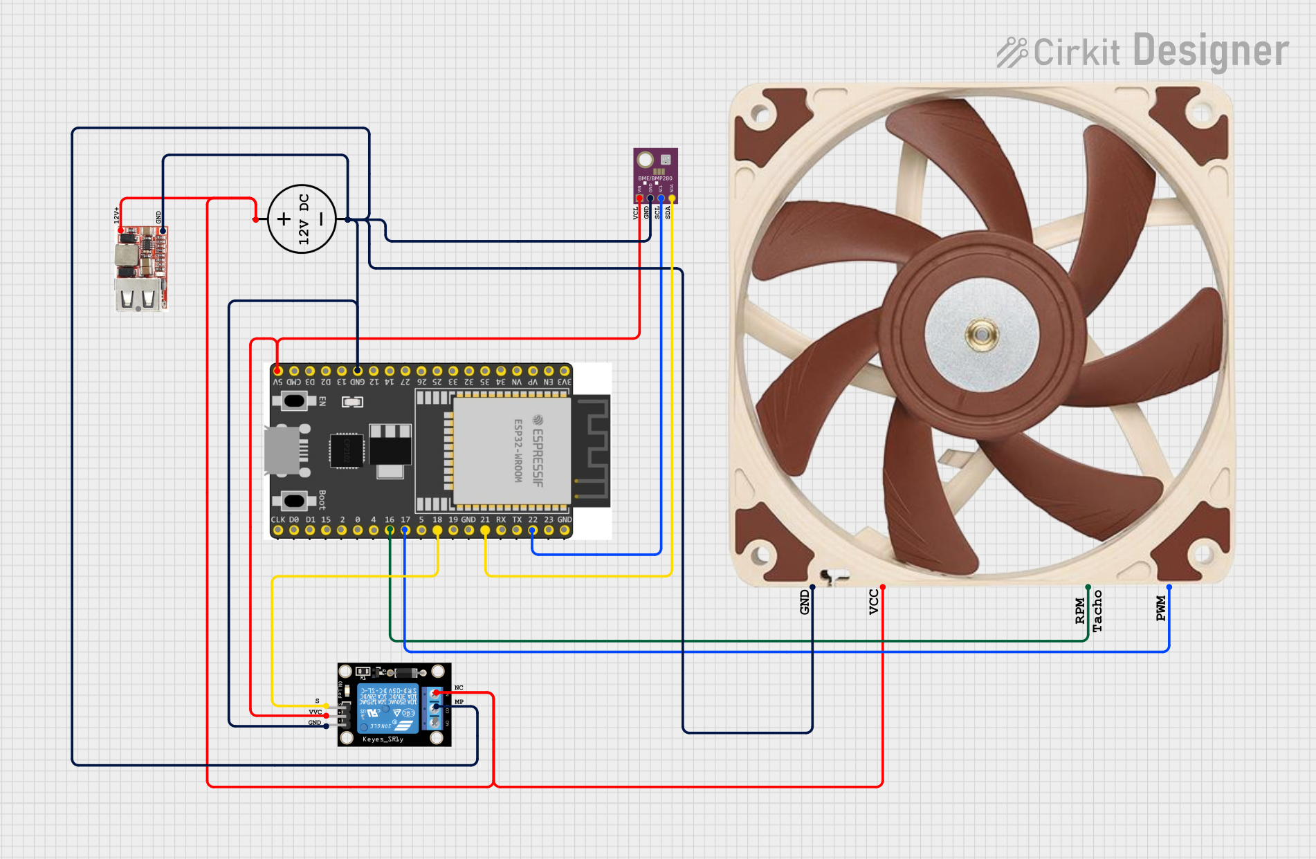
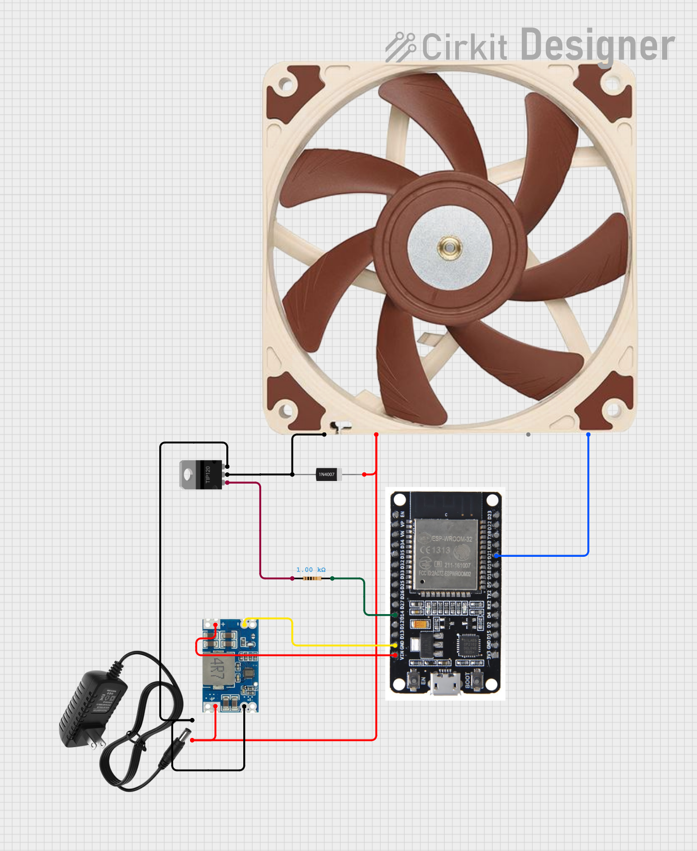

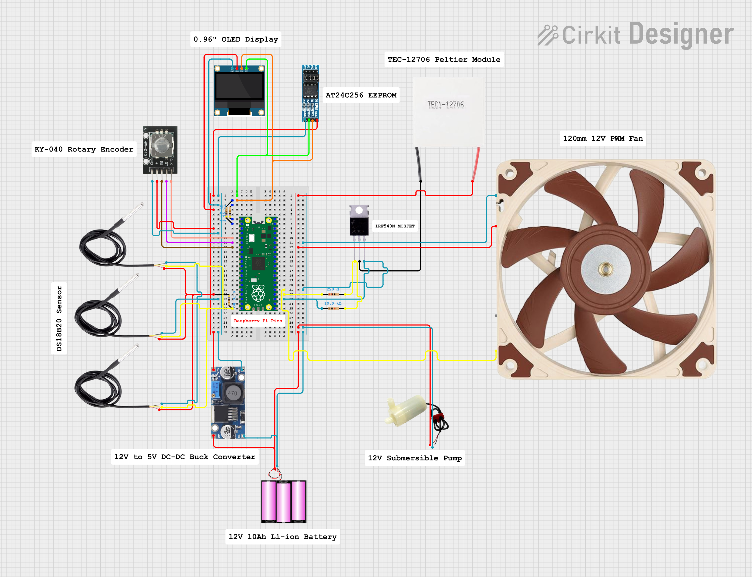
Explore Projects Built with EMC2101 Fan/PWM Controller
Technical Specifications
Key Technical Details
- Supply Voltage (VCC): 3.0V to 3.6V
- Fan Voltage (VFAN): 12V (typical for connected fans)
- Output Current (IOUT): 1A (max for PWM output)
- Operating Temperature Range: -40°C to +85°C
- Communication Interface: SMBus/I²C compatible interface
- Resolution: 8-bit (256 steps) PWM output
- Fan Speed Monitoring: Tachometer input for fan speed feedback
- Additional Features: Over-temperature alarm and fan fault detection
Pin Configuration and Descriptions
| Pin Number | Pin Name | Description |
|---|---|---|
| 1 | VCC | Power supply input (3.0V to 3.6V) |
| 2 | GND | Ground connection |
| 3 | SDA | Serial Data Line for I²C communication |
| 4 | SCL | Serial Clock Line for I²C communication |
| 5 | TACH | Tachometer input for fan speed monitoring |
| 6 | PWM | PWM output to control fan speed |
| 7 | ALERT | Alert output for fault detection and over-temperature |
| 8 | ADDR | Address selection pin for I²C communication |
Usage Instructions
How to Use the EMC2101 in a Circuit
- Power Supply: Connect the VCC pin to a 3.0V to 3.6V power source and the GND pin to the system ground.
- I²C Communication: Connect the SDA and SCL pins to the corresponding I²C data and clock lines on your microcontroller, such as an Arduino UNO.
- Fan Connection: Connect the PWM output pin to the PWM input of your brushless DC fan. Ensure the fan's power supply matches its specifications (typically 12V).
- Tachometer Feedback: Connect the TACH pin to the tachometer output of the fan to monitor its speed.
- Alerts: Optionally, connect the ALERT pin to an input on your microcontroller to receive alerts for over-temperature or fan faults.
Important Considerations and Best Practices
- Ensure that the power supply voltage does not exceed the maximum rating of 3.6V.
- Use pull-up resistors on the SDA and SCL lines as required by the I²C protocol.
- Configure the I²C address of the EMC2101 using the ADDR pin if multiple devices are on the same I²C bus.
- Implement proper filtering and decoupling techniques to minimize noise on the power supply and I²C lines.
- Always monitor the ALERT pin or poll the EMC2101 status registers to handle any fault conditions promptly.
Example Code for Arduino UNO
#include <Wire.h>

// EMC2101 I2C address (check datasheet for variations)
const int EMC2101_Address = 0x4C;

// EMC2101 Register Addresses
const byte CONFIG_REGISTER = 0x20;
const byte PWM_REGISTER = 0x30;

void setup() {
  Wire.begin(); // Initialize I2C
  Serial.begin(9600); // Start serial for output

  // Configure EMC2101
  setFanSpeed(128); // Set fan speed to 50% duty cycle
}

void loop() {
  // Main loop can be used to adjust fan speed based on temperature readings
}

// Function to set the fan speed
void setFanSpeed(byte speed) {
  Wire.beginTransmission(EMC2101_Address);
  Wire.write(PWM_REGISTER); // Point to the PWM register
  Wire.write(speed); // Write the speed value to the register
  Wire.endTransmission();

  Serial.print("Fan speed set to: ");
  Serial.println(speed);
}
Troubleshooting and FAQs
Common Issues
- Fan Not Spinning: Ensure the PWM signal is correctly configured and the fan is powered.
- Inaccurate Speed Control: Verify the PWM frequency and duty cycle match the fan's specifications.
- Communication Errors: Check the I²C connections, pull-up resistors, and address configuration.
Solutions and Tips for Troubleshooting
- Power Supply Issues: Use a multimeter to verify the VCC and GND connections.
- I²C Communication: Use an I²C scanner sketch to confirm the EMC2101 is detected on the bus.
- Alert Handling: Implement an interrupt service routine to handle alerts from the ALERT pin.
FAQs
Q: Can I control multiple fans with one EMC2101? A: The EMC2101 is designed to control a single fan. For multiple fans, use separate controllers or fans with built-in daisy-chaining capability.
Q: What is the maximum PWM frequency the EMC2101 supports? A: Please refer to the EMC2101 datasheet for the maximum PWM frequency specifications.
Q: How do I change the I²C address of the EMC2101? A: The I²C address can be modified by connecting the ADDR pin to VCC or GND as per the datasheet.
Q: Can the EMC2101 be used with 5V systems? A: While the EMC2101 operates at 3.0V to 3.6V, level shifters can be used for interfacing with 5V systems.
This documentation provides a comprehensive guide to using the EMC2101 Fan/PWM Controller. For further details, consult the manufacturer's datasheet and application notes.