How to Use H743 Wlite Usb: Examples, Pinouts, and Specs
Introduction
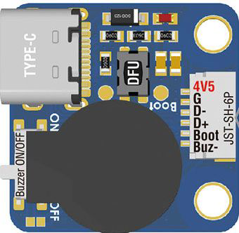
The H743 Wlite USB by Matek is a versatile USB interface module designed for seamless connectivity and communication with a wide range of devices. It is commonly used in embedded systems for data transfer, firmware updates, and as a power supply source. Its compact design and robust performance make it an essential component for prototyping, debugging, and powering small electronic projects.
Explore Projects Built with H743 Wlite Usb


Explore Projects Built with H743 Wlite Usb
Common Applications and Use Cases
- Data transfer between microcontrollers and computers
- Firmware flashing for embedded systems
- Power supply for low-power devices
- USB-to-serial communication in development boards
- Debugging and testing of embedded systems
Technical Specifications
Key Technical Details
| Parameter | Value |
|---|---|
| Manufacturer | Matek |
| Model | H743 Wlite USB |
| Input Voltage | 5V (via USB) |
| Output Voltage | 5V (direct) or 3.3V (regulated) |
| Maximum Output Current | 500mA |
| Communication Protocol | USB 2.0 |
| Operating Temperature | -20°C to 70°C |
| Dimensions | 25mm x 15mm x 5mm |
Pin Configuration and Descriptions
The H743 Wlite USB module features a simple pinout for easy integration into circuits. Below is the pin configuration:
| Pin Name | Description |
|---|---|
| VCC | 5V power output from USB |
| GND | Ground connection |
| TX | Transmit data line for serial communication |
| RX | Receive data line for serial communication |
| 3.3V | Regulated 3.3V power output |
Usage Instructions
How to Use the Component in a Circuit
- Powering Devices: Connect the USB module to a computer or USB power source. Use the
VCCandGNDpins to power your circuit. If your device requires 3.3V, use the3.3Vpin instead ofVCC. - Data Communication: Connect the
TXpin of the H743 Wlite USB to theRXpin of your microcontroller, and theRXpin of the module to theTXpin of your microcontroller. This establishes a serial communication link. - Firmware Updates: Use the USB interface to flash firmware onto compatible microcontrollers or embedded systems.
- Debugging: Monitor serial data from your microcontroller by connecting the module to a computer and using a serial terminal application.
Important Considerations and Best Practices
- Ensure the total current draw of connected devices does not exceed the module's maximum output current of 500mA.
- Use appropriate pull-up or pull-down resistors on the
TXandRXlines if required by your microcontroller. - Avoid shorting the
VCCor3.3Vpins to ground, as this may damage the module. - For long-term use, ensure proper ventilation to prevent overheating.
Example: Connecting to an Arduino UNO
The H743 Wlite USB can be used to establish serial communication with an Arduino UNO. Below is an example code snippet for testing the connection:
// Example: Serial communication with H743 Wlite USB
// This code sends "Hello, World!" to the serial monitor via the USB module.

void setup() {
  Serial.begin(9600); // Initialize serial communication at 9600 baud
  delay(1000);        // Wait for the USB module to initialize
  Serial.println("Hello, World!"); // Send a test message
}

void loop() {
  // Continuously send a message every 2 seconds
  Serial.println("H743 Wlite USB is working!");
  delay(2000);
}
Wiring Instructions:
- Connect the
TXpin of the H743 Wlite USB to theRXpin of the Arduino UNO. - Connect the
RXpin of the H743 Wlite USB to theTXpin of the Arduino UNO. - Connect
GNDof the USB module to theGNDof the Arduino UNO.
Troubleshooting and FAQs
Common Issues and Solutions
No Power Output:
- Ensure the USB cable is properly connected to a power source.
- Verify that the USB cable is functional and supports data transfer (some cables are power-only).
Serial Communication Not Working:
- Double-check the
TXandRXconnections. They must be crossed (TX to RX and RX to TX). - Ensure the baud rate in your code matches the baud rate of the serial terminal.
- Double-check the
Overheating:
- Check that the connected devices do not exceed the 500mA current limit.
- Ensure proper ventilation around the module.
Device Not Recognized by Computer:
- Install the necessary USB drivers for the H743 Wlite USB module.
- Try a different USB port or cable.
FAQs
Q: Can the H743 Wlite USB power a 3.3V device directly?
A: Yes, the module provides a regulated 3.3V output that can be used to power low-power devices.
Q: Is the module compatible with USB 3.0 ports?
A: Yes, the H743 Wlite USB is backward compatible with USB 3.0 ports, but it operates at USB 2.0 speeds.
Q: Can I use this module for programming ESP8266 or ESP32 boards?
A: Yes, the module can be used for programming ESP8266/ESP32 boards, provided the TX and RX connections are correctly configured.
Q: What is the maximum cable length I can use with this module?
A: For reliable communication, it is recommended to use USB cables no longer than 2 meters.
By following this documentation, you can effectively integrate the H743 Wlite USB module into your projects and troubleshoot common issues with ease.