How to Use 10K Potentiometer: Examples, Pinouts, and Specs
10K Potentiometer Documentation
1. Introduction
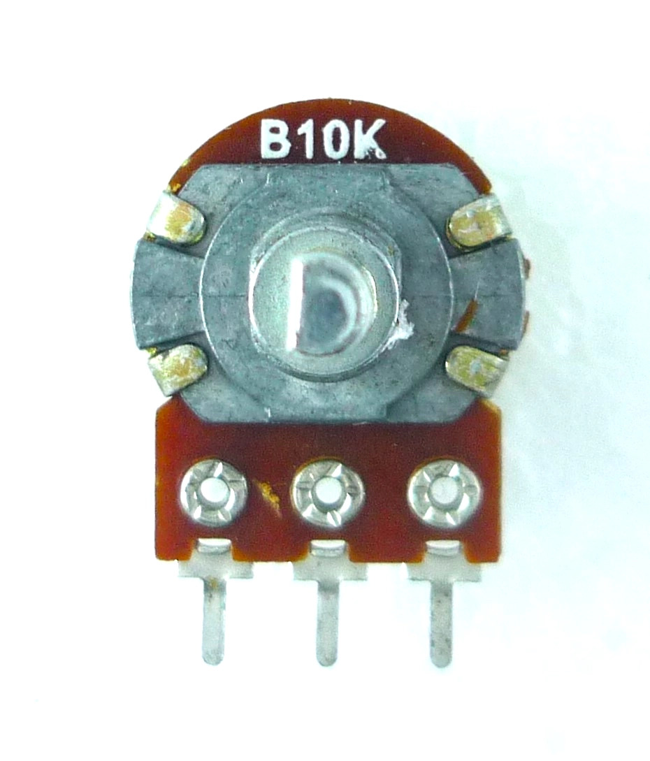
The 10K Potentiometer (Manufacturer: me, Part ID: 10K Potentiometer) is a versatile variable resistor that allows for the adjustment of resistance in an electronic circuit. It is commonly used to control voltage or current and is a fundamental component in many analog and digital applications.
This potentiometer features a resistance range of 0 to 10,000 ohms (10KΩ) and is designed for smooth and precise adjustments. It is widely used in applications such as:
- Volume control in audio devices
- Brightness adjustment in LED circuits
- Sensor calibration in analog systems
- Voltage dividers for microcontroller inputs
- Tuning circuits in radios and oscillators
The 10K Potentiometer is an essential component for both hobbyists and professionals, offering reliability and ease of use in a wide range of projects.
2. Technical Specifications
The following table outlines the key technical details of the 10K Potentiometer:
| Parameter | Value |
|---|---|
| Manufacturer | me |
| Part ID | 10K Potentiometer |
| Resistance Range | 0Ω to 10,000Ω (10KΩ) |
| Tolerance | ±10% |
| Power Rating | 0.25W (1/4 Watt) |
| Operating Voltage | 0V to 50V DC |
| Operating Temperature | -40°C to +85°C |
| Adjustment Type | Rotary (knob or screwdriver) |
| Mounting Type | Through-hole or PCB mount |
| Shaft Length | 15mm |
| Shaft Diameter | 6mm |
Pin Configuration and Descriptions
The 10K Potentiometer typically has three pins:
| Pin Number | Name | Description |
|---|---|---|
| 1 | Terminal 1 | One end of the resistive track. Connect to the input voltage or ground. |
| 2 | Wiper | The adjustable middle pin. Outputs the variable voltage or resistance. |
| 3 | Terminal 2 | The other end of the resistive track. Connect to ground or input voltage. |
3. Usage Instructions
How to Use the 10K Potentiometer in a Circuit
- Identify the Pins: Locate the three pins of the potentiometer. Pin 1 and Pin 3 are the fixed terminals of the resistive track, while Pin 2 (the wiper) provides the variable output.
- Connect the Circuit:
- Connect Pin 1 to the input voltage (e.g., 5V).
- Connect Pin 3 to ground (GND).
- Connect Pin 2 to the input of the device or circuit where you need a variable voltage or resistance.
- Adjust the Resistance: Rotate the potentiometer's shaft to adjust the resistance. Turning the shaft clockwise or counterclockwise will increase or decrease the resistance between the wiper (Pin 2) and the fixed terminals (Pin 1 or Pin 3).
Example Circuit: Voltage Divider
The 10K Potentiometer can be used as a voltage divider to provide a variable voltage output. Here's a simple example:
   +5V ----[ Pin 1 ]----+
                        |
                        [ Resistive Track ]
                        |
   Output ----[ Pin 2 ]--+
                        |
                        GND ----[ Pin 3 ]
In this configuration:
- The voltage at the Output (Pin 2) will vary between 0V and 5V as you rotate the potentiometer.
Important Considerations and Best Practices
- Power Rating: Ensure the power dissipation across the potentiometer does not exceed its rated 0.25W.
- Avoid Overturning: Do not force the potentiometer beyond its mechanical limits to prevent damage.
- Debouncing: When used in digital circuits, consider software debouncing to handle noise caused by mechanical adjustments.
- Mounting: Secure the potentiometer properly to avoid loose connections or mechanical stress.
4. Arduino Example Code
The 10K Potentiometer is commonly used with microcontrollers like the Arduino UNO to read analog input values. Below is an example code to read the potentiometer's output and display the value in the Serial Monitor.
// Arduino Example: Reading a 10K Potentiometer
// Connect Pin 1 to 5V, Pin 3 to GND, and Pin 2 to an analog input (A0).

const int potPin = A0; // Pin where the potentiometer wiper (Pin 2) is connected

void setup() {
  Serial.begin(9600); // Initialize serial communication at 9600 baud
}

void loop() {
  int potValue = analogRead(potPin); // Read the analog value (0-1023)

  // Convert the analog value to a voltage (assuming 5V reference)
  float voltage = potValue * (5.0 / 1023.0);

  // Print the values to the Serial Monitor
  Serial.print("Analog Value: ");
  Serial.print(potValue);
  Serial.print(" | Voltage: ");
  Serial.print(voltage);
  Serial.println(" V");

  delay(500); // Wait for 500ms before the next reading
}
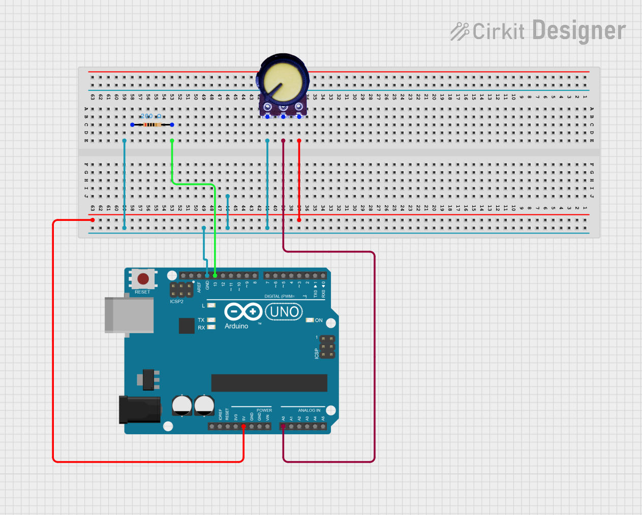
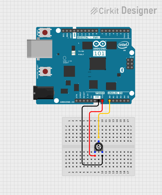
Circuit Connection for Arduino:
- Pin 1: Connect to Arduino 5V.
- Pin 3: Connect to Arduino GND.
- Pin 2: Connect to Arduino A0.
5. Troubleshooting and FAQs
Common Issues and Solutions
| Issue | Possible Cause | Solution |
|---|---|---|
| No output voltage from the wiper (Pin 2) | Incorrect wiring | Verify the connections to Pin 1, Pin 2, and Pin 3. Ensure proper voltage input. |
| Output voltage is unstable | Mechanical noise or loose connections | Secure the potentiometer and use software debouncing if connected to a microcontroller. |
| Potentiometer is not adjusting smoothly | Dust or wear on the resistive track | Clean the potentiometer or replace it if worn out. |
| Overheating | Exceeding power rating | Ensure the power dissipation is within the 0.25W limit. |
Frequently Asked Questions
Can I use the 10K Potentiometer for AC signals?
- Yes, but ensure the AC voltage and current are within the component's ratings.
What happens if I reverse the connections to Pin 1 and Pin 3?
- The potentiometer will still function, but the direction of adjustment (clockwise/counterclockwise) will be reversed.
Can I use the potentiometer as a variable resistor (rheostat)?
- Yes, connect only two pins: the wiper (Pin 2) and one of the fixed terminals (Pin 1 or Pin 3).
What is the lifespan of the potentiometer?
- The typical lifespan is around 10,000 to 50,000 cycles, depending on usage and environmental conditions.
This documentation provides a comprehensive guide to understanding, using, and troubleshooting the 10K Potentiometer. For further assistance, please contact the manufacturer (me) or refer to additional resources.
Explore Projects Built with 10K Potentiometer


Explore Projects Built with 10K Potentiometer