How to Use LR44/AG13 Button Cell: Examples, Pinouts, and Specs
Introduction
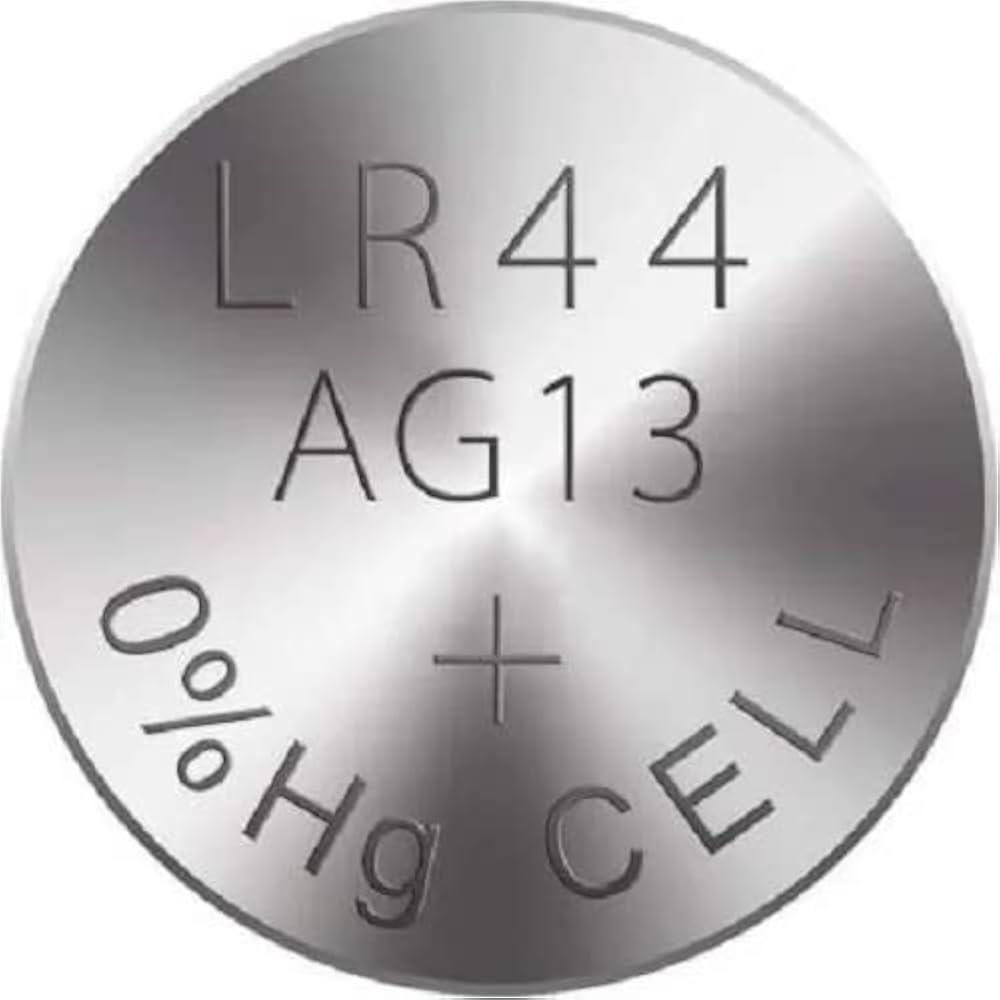
The LR44/AG13 button cell, manufactured by Duracell (Manufacturer Part ID: AG13), is a small, round, non-rechargeable battery widely used in compact electronic devices. It provides a nominal voltage of 1.5V and is known for its reliable performance and long shelf life. This battery is commonly found in devices such as watches, calculators, laser pointers, toys, and small medical instruments like digital thermometers.
Explore Projects Built with LR44/AG13 Button Cell
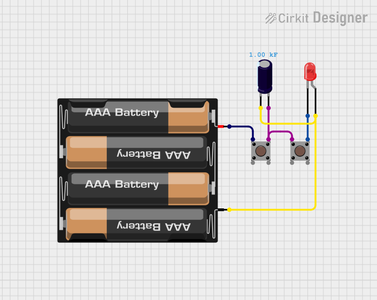
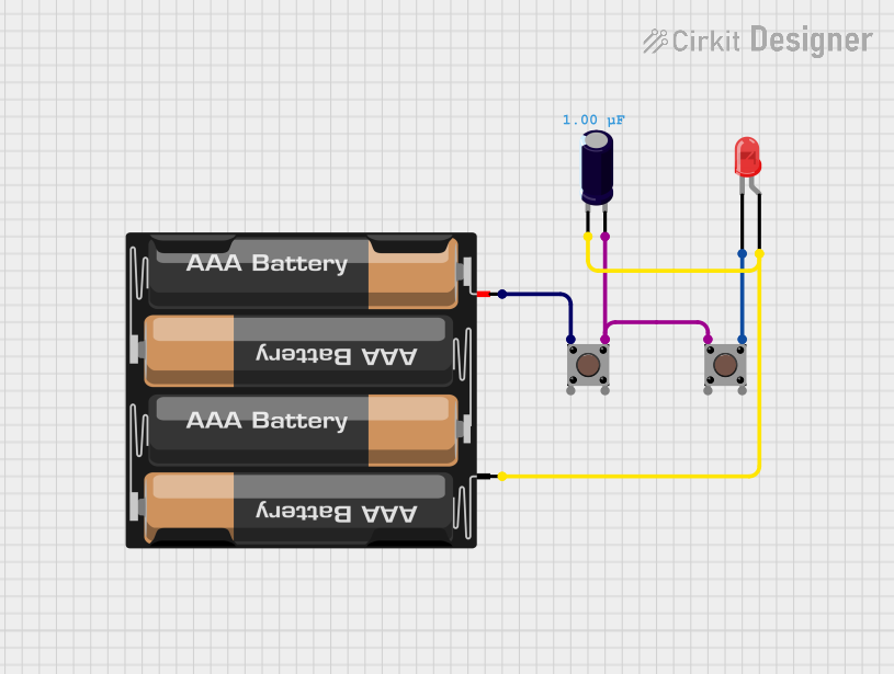
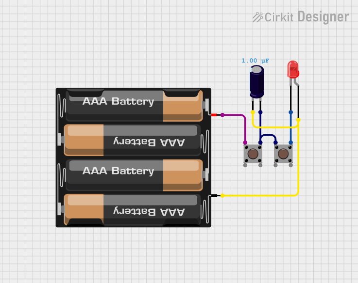

Explore Projects Built with LR44/AG13 Button Cell
Technical Specifications
The LR44/AG13 button cell is designed to deliver consistent power for low-drain devices. Below are its key technical specifications:
| Parameter | Specification |
|---|---|
| Manufacturer | Duracell |
| Manufacturer Part ID | AG13 |
| Battery Type | Alkaline |
| Nominal Voltage | 1.5V |
| Nominal Capacity | ~110-130 mAh |
| Diameter | 11.6 mm |
| Height | 5.4 mm |
| Weight | ~2 grams |
| Operating Temperature | -10°C to 50°C |
| Shelf Life | Up to 5 years |
Pin Configuration and Descriptions
The LR44/AG13 button cell has two terminals:
| Terminal | Description |
|---|---|
| Positive (+) | The flat side of the battery, marked with a "+" symbol. |
| Negative (-) | The rounded side of the battery. |
Usage Instructions
How to Use the LR44/AG13 Button Cell in a Circuit
- Identify the Terminals: Ensure you correctly identify the positive (+) and negative (-) terminals of the battery.
- Insert into Battery Holder: Place the battery into a compatible battery holder or device, ensuring proper polarity alignment.
- Connect to Circuit: If using in a custom circuit, connect the positive terminal to the positive rail and the negative terminal to the ground rail.
- Power the Device: Once connected, the battery will supply 1.5V to the circuit.
Important Considerations and Best Practices
- Polarity: Always ensure the correct polarity when inserting the battery into a device or circuit. Reversing the polarity may damage the device.
- Battery Holder: Use a secure and appropriately sized battery holder to prevent accidental disconnection.
- Avoid Short Circuits: Do not short-circuit the terminals, as this can cause the battery to overheat or leak.
- Storage: Store unused batteries in a cool, dry place to maximize shelf life.
- Disposal: Dispose of used batteries responsibly, following local recycling regulations.
Example: Using LR44/AG13 with an Arduino UNO
While the LR44/AG13 is not directly compatible with Arduino UNO due to its low voltage, it can be used to power small peripheral devices like sensors or LEDs. Below is an example of using the LR44/AG13 to power an LED:
Circuit Diagram
- Connect the positive terminal of the LR44/AG13 to the anode (+) of the LED.
- Connect the cathode (-) of the LED to a 220-ohm resistor.
- Connect the other end of the resistor to the negative terminal of the battery.
Code Example
No code is required for this simple circuit, as the LED is powered directly by the battery.
Troubleshooting and FAQs
Common Issues and Solutions
Device Not Powering On:
- Cause: Incorrect polarity or depleted battery.
- Solution: Check the polarity and replace the battery if necessary.
Battery Leaking:
- Cause: Overuse or exposure to high temperatures.
- Solution: Replace the battery immediately and clean the device contacts.
Short Battery Life:
- Cause: High-drain device or continuous use.
- Solution: Use a battery with higher capacity or turn off the device when not in use.
Corroded Terminals:
- Cause: Prolonged exposure to moisture.
- Solution: Clean the terminals with a dry cloth or isopropyl alcohol.
FAQs
Q1: Can the LR44/AG13 be recharged?
A1: No, the LR44/AG13 is a non-rechargeable alkaline battery. Attempting to recharge it may cause leakage or explosion.
Q2: What is the difference between LR44 and AG13?
A2: LR44 and AG13 are interchangeable names for the same battery type. "LR44" is the IEC designation, while "AG13" is a common manufacturer designation.
Q3: Can I use an LR44/AG13 in place of an SR44 battery?
A3: While both have the same size, the SR44 (silver oxide) battery has a higher capacity and more stable voltage. Use SR44 if your device requires it.
Q4: How do I know when the battery is depleted?
A4: Devices may stop functioning or display a low-battery warning. You can also measure the voltage with a multimeter; if it drops below 1.2V, the battery is near depletion.
By following this documentation, users can effectively utilize the LR44/AG13 button cell in their devices and circuits.