How to Use BQ25185 USB DC Solar Charger with 5V Boost: Examples, Pinouts, and Specs
Introduction
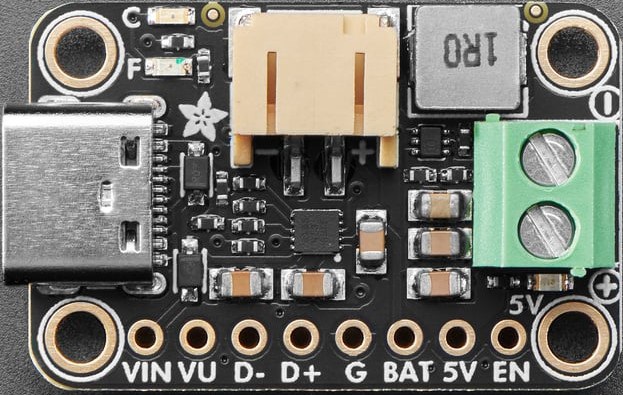
The BQ25185 USB DC Solar Charger with 5V Boost (Adafruit Part ID: 6106) is a highly integrated battery management IC designed for efficient solar charging applications. It supports USB input, solar panel input, and features a 5V boost output to charge batteries or power external devices. This component is ideal for portable, low-power, and renewable energy projects.
Explore Projects Built with BQ25185 USB DC Solar Charger with 5V Boost
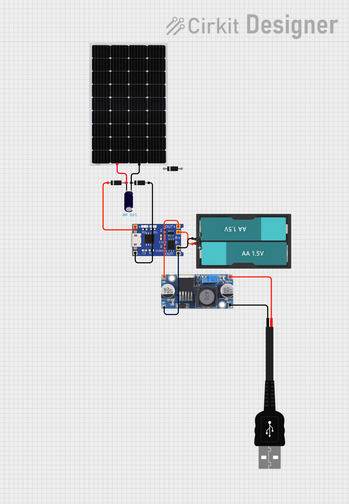
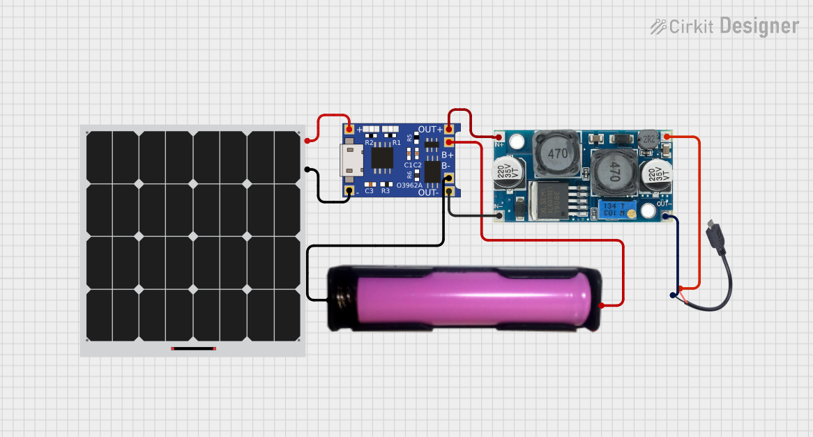

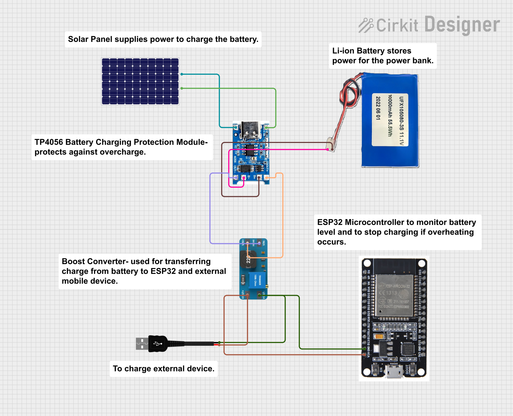
Explore Projects Built with BQ25185 USB DC Solar Charger with 5V Boost
Common Applications and Use Cases
- Solar-powered IoT devices
- Portable battery-powered systems
- Wearable electronics
- USB-powered battery charging
- Backup power systems
Technical Specifications
The following table outlines the key technical details of the BQ25185:
| Parameter | Value |
|---|---|
| Input Voltage Range | 3.5V to 6.5V |
| Output Voltage (Boost Mode) | 5V |
| Battery Charging Voltage | Configurable up to 4.2V |
| Maximum Charging Current | 500mA |
| Boost Output Current | Up to 1A |
| Efficiency | Up to 90% (depending on input/output load) |
| Operating Temperature Range | -40°C to +85°C |
Pin Configuration and Descriptions
The BQ25185 IC has multiple pins for power input, output, and control. Below is the pin configuration:
| Pin Name | Type | Description |
|---|---|---|
| VIN | Power Input | Main input for USB or solar panel (3.5V to 6.5V). |
| BAT | Power Output | Connects to the positive terminal of the battery. |
| SYS | Power Output | System output for powering external devices. |
| BOOST | Power Output | 5V boost output for powering devices directly. |
| GND | Ground | Ground connection. |
| EN | Control Input | Enable pin to turn the IC on or off. |
| STAT | Status Output | Status indicator pin for charging (can be connected to an LED). |
| ISET | Control Input | Configures the charging current using an external resistor. |
| TS | Control Input | Temperature sense input for monitoring battery temperature. |
| SDA | Data I/O | I2C data line for communication with a microcontroller. |
| SCL | Clock Input | I2C clock line for communication with a microcontroller. |
Usage Instructions
How to Use the Component in a Circuit
- Power Input: Connect a USB power source or a solar panel to the
VINpin. Ensure the input voltage is within the range of 3.5V to 6.5V. - Battery Connection: Attach a single-cell Li-Ion or Li-Polymer battery to the
BATpin. The IC will manage charging automatically. - Boost Output: Use the
BOOSTpin to power external devices requiring 5V. Ensure the load does not exceed 1A. - System Output: The
SYSpin provides power directly from the battery or input source, depending on availability. - I2C Communication: Connect the
SDAandSCLpins to a microcontroller (e.g., Arduino UNO) for advanced configuration and monitoring.
Important Considerations and Best Practices
- Use a decoupling capacitor (e.g., 10µF) between
VINandGNDto stabilize the input voltage. - Place a resistor on the
ISETpin to set the desired charging current. Refer to the datasheet for resistor values. - Monitor the
STATpin to determine the charging status. Connect it to an LED for visual feedback. - Ensure proper heat dissipation if operating at high currents for extended periods.
- For solar panel input, use a panel with an open-circuit voltage within the supported range (3.5V to 6.5V).
Example Arduino Code
The following example demonstrates how to monitor the charging status of the BQ25185 using an Arduino UNO:
#include <Wire.h> // Include the Wire library for I2C communication

#define BQ25185_I2C_ADDRESS 0x6B // Default I2C address of the BQ25185

void setup() {
  Serial.begin(9600); // Initialize serial communication
  Wire.begin();       // Initialize I2C communication

  Serial.println("BQ25185 Charger Monitoring");
}

void loop() {
  Wire.beginTransmission(BQ25185_I2C_ADDRESS);
  Wire.write(0x00); // Address of the status register
  Wire.endTransmission();

  Wire.requestFrom(BQ25185_I2C_ADDRESS, 1); // Request 1 byte from the status register
  if (Wire.available()) {
    byte status = Wire.read(); // Read the status byte

    // Check the charging status bits (refer to the datasheet for bit definitions)
    if (status & 0x01) {
      Serial.println("Charging in progress...");
    } else if (status & 0x02) {
      Serial.println("Charging complete.");
    } else {
      Serial.println("No charging activity.");
    }
  }

  delay(1000); // Wait for 1 second before checking again
}
Troubleshooting and FAQs
Common Issues and Solutions
No Output Voltage on BOOST Pin
- Ensure the
ENpin is pulled high to enable the IC. - Verify that the input voltage is within the specified range (3.5V to 6.5V).
- Check for proper connections and ensure the load does not exceed 1A.
- Ensure the
Battery Not Charging
- Confirm that the battery is connected correctly to the
BATpin. - Check the
ISETresistor value to ensure the charging current is set appropriately. - Verify the input voltage is sufficient for charging.
- Confirm that the battery is connected correctly to the
Overheating
- Reduce the load on the
BOOSTorSYSpins. - Ensure adequate ventilation or add a heatsink if necessary.
- Reduce the load on the
I2C Communication Fails
- Verify the
SDAandSCLconnections to the microcontroller. - Check the I2C address (default: 0x6B) and ensure no address conflicts.
- Verify the
FAQs
Q: Can I use this IC with a 12V solar panel?
A: No, the input voltage range is limited to 3.5V to 6.5V. Use a step-down converter to reduce the voltage.
Q: What type of battery is supported?
A: The BQ25185 supports single-cell Li-Ion or Li-Polymer batteries.
Q: How do I configure the charging current?
A: Use an external resistor on the ISET pin. Refer to the datasheet for the resistor-to-current mapping.
Q: Can I power the system without a battery?
A: Yes, the SYS pin can provide power directly from the input source if no battery is connected.