
How to Use GX16 4pin: Examples, Pinouts, and Specs
 Design with GX16 4pin in Cirkit Designer
Introduction
The GX16 4-pin connector, manufactured by Base (Part ID: GX16 4pin), is a circular electrical connector designed for secure and reliable electrical connections. It features four pins, making it suitable for transmitting signals or power in various applications. Known for its durability and ease of use, the GX16 4-pin connector is widely used in audio equipment, lighting systems, industrial machinery, and robotics.
Explore Projects Built with GX16 4pin
 Open Project in Cirkit Designer
 Open Project in Cirkit Designer
 Open Project in Cirkit Designer
 Open Project in Cirkit Designer
Explore Projects Built with GX16 4pin
Open Project in Cirkit DesignerOpen Project in Cirkit DesignerOpen Project in Cirkit DesignerOpen Project in Cirkit DesignerCommon Applications
- Audio equipment (e.g., microphones, speakers)
- Lighting systems (e.g., stage lighting, LED setups)
- Industrial machinery and automation
- Robotics and control systems
- Custom DIY electronics projects
Technical Specifications
Key Technical Details
| Parameter | Value |
|---|---|
| Manufacturer | Base |
| Part ID | GX16 4pin |
| Number of Pins | 4 |
| Connector Type | Circular |
| Rated Voltage | 250V AC |
| Rated Current | 5A |
| Contact Resistance | ≤ 0.005 Ω |
| Insulation Resistance | ≥ 1000 MΩ |
| Operating Temperature | -50°C to +70°C |
| Material (Shell) | Zinc alloy with nickel plating |
| Material (Contacts) | Brass with silver plating |
| Mounting Style | Panel mount or cable mount |
Pin Configuration and Descriptions
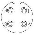
The GX16 4-pin connector has four pins arranged in a circular pattern. Below is the pin configuration:
| Pin Number | Description | Typical Use Case |
|---|---|---|
| 1 | Signal/Power Line 1 | Positive voltage or data |
| 2 | Signal/Power Line 2 | Ground or data |
| 3 | Signal/Power Line 3 | Positive voltage or data |
| 4 | Signal/Power Line 4 | Ground or data |
Note: The pin assignments may vary depending on the application. Always refer to your circuit design or device manual for proper wiring.
Usage Instructions
How to Use the GX16 4-pin Connector in a Circuit
Wiring the Connector:
- Identify the pin numbers on the connector (usually marked on the connector itself).
- Solder the wires to the corresponding pins. Use heat shrink tubing to insulate the connections for safety.
- For panel-mounted connectors, secure the connector to the panel using the provided nut.
Connecting the Mating Parts:
- Align the male and female connectors using the alignment notch.
- Push the connectors together and twist the locking ring to secure the connection.
Testing the Connection:
- Use a multimeter to verify continuity between the connected pins.
- Ensure there are no short circuits between adjacent pins.
Important Considerations and Best Practices
- Avoid Overloading: Do not exceed the rated voltage (250V AC) or current (5A) to prevent damage.
- Proper Insulation: Ensure all soldered connections are insulated to avoid short circuits.
- Environmental Protection: If used in harsh environments, consider additional sealing to protect against moisture and dust.
- Pin Assignment: Double-check the pin assignments before connecting to avoid incorrect wiring.
Example: Connecting to an Arduino UNO
The GX16 4-pin connector can be used to interface external devices (e.g., sensors or actuators) with an Arduino UNO. Below is an example of how to connect a sensor using the GX16 4-pin connector.
Wiring Diagram
- Pin 1: VCC (5V from Arduino UNO)
- Pin 2: GND (Ground from Arduino UNO)
- Pin 3: Signal (Sensor output to Arduino input pin)
- Pin 4: Not used (optional)
Arduino Code Example
// Example code for reading a sensor connected via GX16 4-pin connector
const int sensorPin = A0; // Sensor signal connected to analog pin A0
int sensorValue = 0;      // Variable to store sensor reading

void setup() {
  Serial.begin(9600); // Initialize serial communication at 9600 baud
  pinMode(sensorPin, INPUT); // Set sensor pin as input
}

void loop() {
  sensorValue = analogRead(sensorPin); // Read the sensor value
  Serial.print("Sensor Value: ");      // Print the sensor value to the serial monitor
  Serial.println(sensorValue);
  delay(500); // Wait for 500ms before the next reading
}
Note: Ensure the sensor's voltage and current requirements are compatible with the Arduino UNO.
Troubleshooting and FAQs
Common Issues and Solutions
| Issue | Possible Cause | Solution |
|---|---|---|
| No signal or power transmission | Incorrect wiring or loose connection | Verify wiring and ensure connectors are securely fastened. |
| Short circuit between pins | Poor soldering or exposed wires | Inspect solder joints and insulate exposed wires. |
| Connector does not fit properly | Misalignment of male and female parts | Align the connectors using the alignment notch. |
| Signal interference or noise | Poor shielding or grounding | Use shielded cables and ensure proper grounding. |
FAQs
Can the GX16 4-pin connector be used outdoors?
- The connector is not inherently waterproof. For outdoor use, additional sealing or waterproofing is recommended.
What tools are needed to assemble the connector?
- You will need a soldering iron, solder, heat shrink tubing, and a small wrench for securing the panel mount.
Can I use the GX16 4-pin connector for high-frequency signals?
- While it can handle low-frequency signals well, it may not be suitable for high-frequency applications due to potential signal loss.
Is the connector compatible with other GX16 variants?
- The GX16 4-pin connector is only compatible with other GX16 connectors that have the same pin count and configuration.
By following this documentation, you can effectively use the GX16 4-pin connector in your projects and troubleshoot common issues with ease.