
How to Use GE864: Examples, Pinouts, and Specs

 Design with GE864 in Cirkit Designer
Introduction
The GE864 is a compact GSM/GPRS module designed for wireless communication in embedded systems. It supports quad-band GSM/GPRS connectivity, making it suitable for global applications. The module is widely used in Internet of Things (IoT) applications, including remote monitoring, telemetry, asset tracking, and industrial automation. Its small form factor and low power consumption make it ideal for space-constrained and battery-powered devices.
Explore Projects Built with GE864
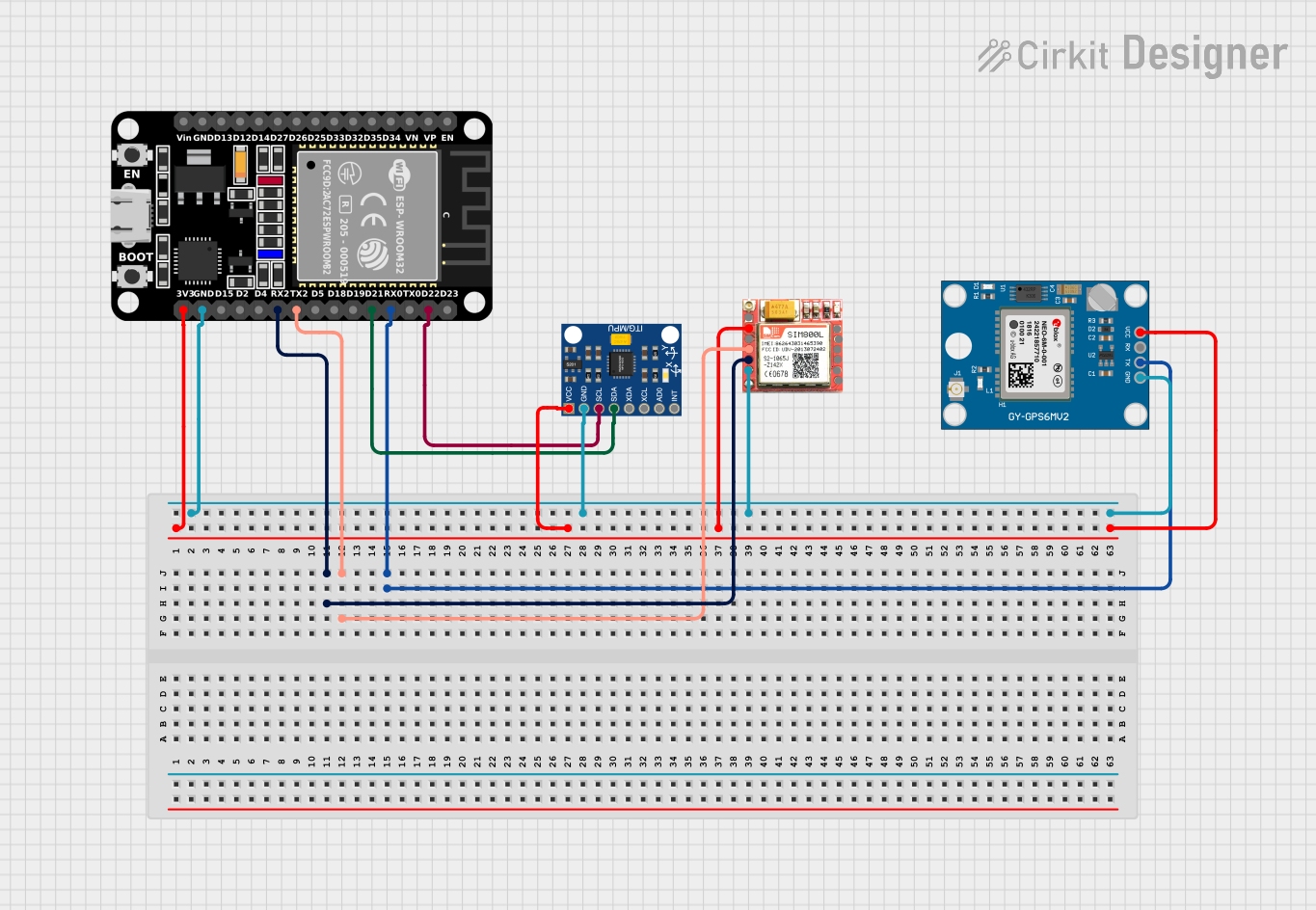 Open Project in Cirkit Designer
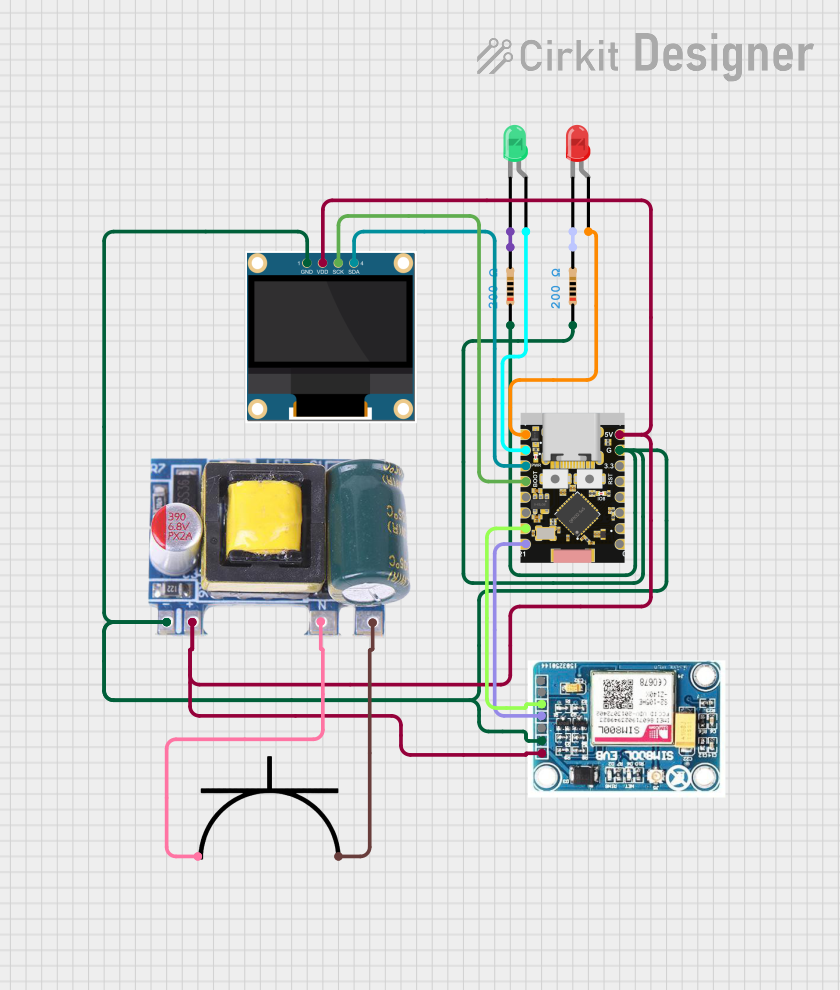 Open Project in Cirkit Designer
 Open Project in Cirkit Designer
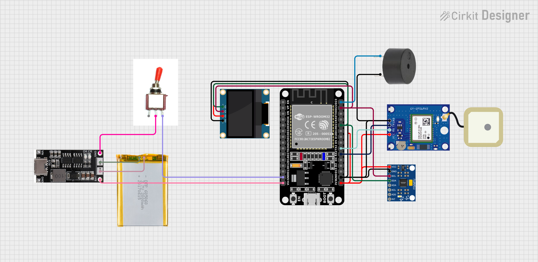 Open Project in Cirkit Designer
Explore Projects Built with GE864
Open Project in Cirkit DesignerOpen Project in Cirkit DesignerOpen Project in Cirkit DesignerOpen Project in Cirkit DesignerTechnical Specifications
The GE864 module offers robust performance and versatile features for wireless communication. Below are its key technical specifications:
General Specifications
- Frequency Bands: Quad-band GSM 850/900/1800/1900 MHz
- GPRS Class: Class 10 (up to 85.6 kbps)
- Supply Voltage: 3.22V to 4.5V
- Power Consumption:
- Idle: ~1.5 mA
- GPRS transmission: ~250 mA (average)
- Operating Temperature: -40°C to +85°C
- Dimensions: 30 mm x 30 mm x 2.8 mm
- Weight: ~7 g
Pin Configuration and Descriptions
The GE864 module has a 60-pin LGA (Land Grid Array) interface. Below is a summary of the key pins:
| Pin Number | Pin Name | Description |
|---|---|---|
| 1 | VBATT | Main power supply input (3.22V to 4.5V). |
| 2 | GND | Ground connection. |
| 3 | TXD | UART Transmit Data (connect to RXD of host MCU). |
| 4 | RXD | UART Receive Data (connect to TXD of host MCU). |
| 5 | RTS | UART Request to Send (optional hardware flow control). |
| 6 | CTS | UART Clear to Send (optional hardware flow control). |
| 7 | ON/OFF | Power-on control pin (active low). |
| 8 | RESET | Hardware reset pin (active low). |
| 9 | ADC_IN | Analog-to-digital converter input (0V to 2.8V). |
| 10 | GPIO1 | General-purpose I/O pin 1. |
| 11 | GPIO2 | General-purpose I/O pin 2. |
| 12 | NETLIGHT | Network status indicator (connect to an LED). |
| 13 | ANT | RF antenna connection (50Ω impedance). |
Note: For a complete pinout, refer to the official GE864 datasheet.
Usage Instructions
How to Use the GE864 in a Circuit
- Power Supply: Ensure the module is powered with a stable voltage between 3.22V and 4.5V. Use decoupling capacitors close to the VBATT pin to minimize noise.
- UART Communication: Connect the TXD and RXD pins to the corresponding RXD and TXD pins of your microcontroller. If hardware flow control is required, connect RTS and CTS as well.
- Antenna Connection: Attach a 50Ω impedance antenna to the ANT pin for optimal signal reception and transmission.
- Power-On Sequence:
- Pull the ON/OFF pin low for at least 1 second to power on the module.
- Wait for the module to initialize (indicated by the NETLIGHT pin behavior).
- SIM Card: Insert a valid SIM card into the SIM holder (if applicable) and ensure proper orientation.
Important Considerations
- Antenna Placement: Place the antenna away from noise sources and ensure it is not obstructed by metal enclosures.
- UART Voltage Levels: Ensure the UART voltage levels are compatible with your microcontroller (typically 2.8V logic for the GE864).
- Power Supply Stability: Use a low-noise power supply to avoid communication issues.
- Firmware Updates: Check for firmware updates from the manufacturer to ensure compatibility and performance.
Example: Connecting GE864 to Arduino UNO
Below is an example of how to interface the GE864 module with an Arduino UNO for sending an SMS:
Circuit Connections
- GE864 TXD → Arduino RX (Pin 0)
- GE864 RXD → Arduino TX (Pin 1)
- GE864 GND → Arduino GND
- GE864 VBATT → 3.7V Li-ion Battery or Regulated 3.7V Supply
- GE864 ON/OFF → Arduino Digital Pin 7
Arduino Code
#include <SoftwareSerial.h>

// Define software serial pins for communication with GE864
SoftwareSerial ge864Serial(10, 11); // RX, TX

// Define the ON/OFF pin for the GE864 module
const int powerPin = 7;

void setup() {
  // Initialize serial communication
  Serial.begin(9600); // For debugging
  ge864Serial.begin(9600); // For GE864 communication

  // Configure the power pin
  pinMode(powerPin, OUTPUT);
  digitalWrite(powerPin, HIGH); // Ensure the module is off initially

  // Power on the GE864 module
  powerOnGE864();

  // Send an SMS
  sendSMS("+1234567890", "Hello from GE864!");
}

void loop() {
  // Continuously check for incoming data from the GE864 module
  if (ge864Serial.available()) {
    Serial.write(ge864Serial.read());
  }
}

void powerOnGE864() {
  // Pull the ON/OFF pin low for 1 second to power on the module
  digitalWrite(powerPin, LOW);
  delay(1000);
  digitalWrite(powerPin, HIGH);
  delay(5000); // Wait for the module to initialize
}

void sendSMS(const char* phoneNumber, const char* message) {
  // Send AT commands to configure and send an SMS
  ge864Serial.println("AT"); // Check communication
  delay(1000);

  ge864Serial.println("AT+CMGF=1"); // Set SMS mode to text
  delay(1000);

  ge864Serial.print("AT+CMGS=\"");
  ge864Serial.print(phoneNumber);
  ge864Serial.println("\""); // Set recipient phone number
  delay(1000);

  ge864Serial.print(message); // Write the SMS message
  delay(1000);

  ge864Serial.write(26); // Send Ctrl+Z to send the SMS
  delay(5000); // Wait for the SMS to be sent
}
Note: Replace
+1234567890with the recipient's phone number.
Troubleshooting and FAQs
Common Issues
Module Not Powering On:
- Ensure the VBATT voltage is within the specified range (3.22V to 4.5V).
- Verify the ON/OFF pin is pulled low for at least 1 second during the power-on sequence.
No Network Connection:
- Check the antenna connection and placement.
- Ensure the SIM card is inserted correctly and has an active subscription.
- Verify the module is operating in a location with sufficient GSM signal strength.
UART Communication Issues:
- Confirm the UART voltage levels are compatible between the GE864 and the microcontroller.
- Check the baud rate settings (default is 9600 bps).
SMS Not Sending:
- Ensure the SIM card has sufficient balance for sending SMS.
- Verify the phone number format (e.g., include the country code).
Tips for Troubleshooting
- Use an oscilloscope or logic analyzer to monitor UART signals for debugging.
- Check the NETLIGHT pin behavior to diagnose network status:
- Fast blinking: Searching for network.
- Slow blinking: Connected to the network.
- Refer to the AT command manual for advanced debugging and configuration.