How to Use Power Module GM V1.0: Examples, Pinouts, and Specs
Introduction
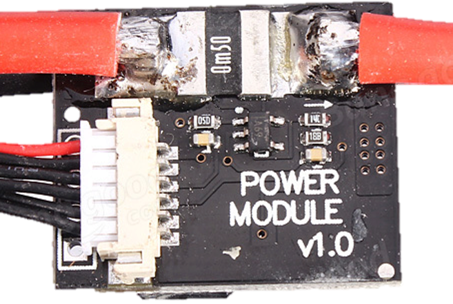
The Power Module GM V1.0 is a versatile power supply module designed to provide stable voltage and current for a wide range of electronic projects. It features adjustable output settings, allowing users to fine-tune the voltage and current to meet the specific requirements of their circuits. Additionally, the module is equipped with built-in protection mechanisms, such as overcurrent and thermal protection, ensuring safe and reliable operation.
Explore Projects Built with Power Module GM V1.0


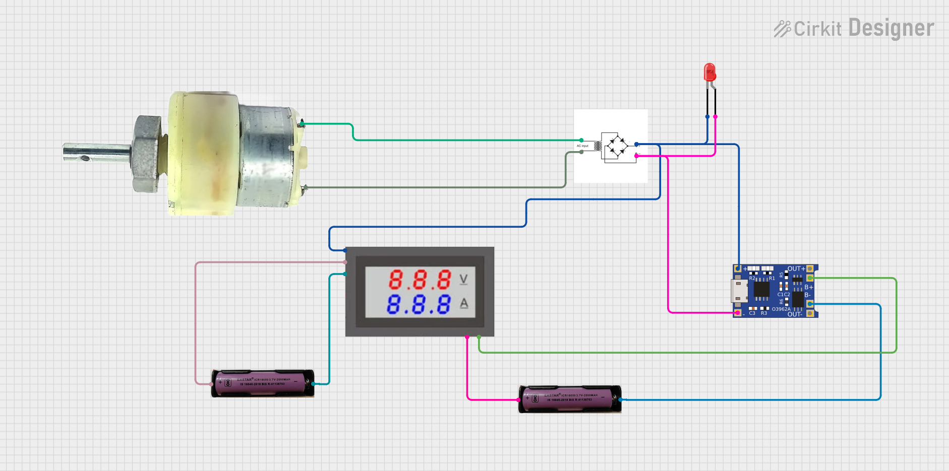
Explore Projects Built with Power Module GM V1.0
Common Applications and Use Cases
- Powering microcontroller-based projects (e.g., Arduino, Raspberry Pi)
- Supplying regulated power to sensors, motors, and other peripherals
- Prototyping and testing electronic circuits
- Educational and DIY electronics projects
Technical Specifications
Key Technical Details
| Parameter | Value |
|---|---|
| Input Voltage Range | 6V to 24V DC |
| Output Voltage Range | 3.3V to 12V DC (adjustable) |
| Maximum Output Current | 2A |
| Efficiency | Up to 90% |
| Protection Features | Overcurrent, Overvoltage, Thermal |
| Dimensions | 50mm x 25mm x 15mm |
Pin Configuration and Descriptions
| Pin Name | Type | Description |
|---|---|---|
| VIN | Input | Connect to the positive terminal of the power source (6V-24V DC). |
| GND | Ground | Connect to the negative terminal of the power source. |
| VOUT | Output | Provides the regulated output voltage (3.3V-12V DC). |
| ADJ | Adjustment | Used to adjust the output voltage using a potentiometer. |
Usage Instructions
How to Use the Power Module GM V1.0 in a Circuit
Connect the Input Voltage:
- Attach the VIN pin to the positive terminal of your power source (e.g., a DC adapter or battery).
- Connect the GND pin to the negative terminal of the power source.
Adjust the Output Voltage:
- Use the onboard potentiometer to set the desired output voltage. Turn the potentiometer clockwise to increase the voltage and counterclockwise to decrease it.
- Use a multimeter to measure the output voltage at the VOUT pin for precise adjustment.
Connect the Load:
- Attach the VOUT pin to the positive terminal of your load (e.g., a microcontroller or sensor).
- Connect the GND pin to the ground of your load.
Verify Connections:
- Double-check all connections to ensure proper polarity and secure wiring.
Power On:
- Turn on the power source and verify that the module is providing the correct output voltage and current.
Important Considerations and Best Practices
- Ensure that the input voltage is within the specified range (6V-24V DC) to avoid damaging the module.
- Do not exceed the maximum output current of 2A to prevent overheating or triggering the overcurrent protection.
- Use a heatsink or active cooling if the module operates at high currents for extended periods.
- Avoid short circuits at the output to prevent damage to the module or connected devices.
Example: Using the Power Module GM V1.0 with an Arduino UNO
To power an Arduino UNO with the Power Module GM V1.0:
- Set the output voltage to 5V using the potentiometer.
- Connect the VOUT pin to the Arduino's 5V pin.
- Connect the GND pin to the Arduino's GND pin.
- Power the module with a 9V DC adapter connected to the VIN and GND pins.
Here is an example Arduino code to blink an LED while powered by the module:
// Simple LED Blink Example
// This code assumes an LED is connected to pin 13 of the Arduino UNO.

void setup() {
  pinMode(13, OUTPUT); // Set pin 13 as an output
}

void loop() {
  digitalWrite(13, HIGH); // Turn the LED on
  delay(1000);            // Wait for 1 second
  digitalWrite(13, LOW);  // Turn the LED off
  delay(1000);            // Wait for 1 second
}
Troubleshooting and FAQs
Common Issues and Solutions
No Output Voltage:
- Cause: Input voltage is not connected or is outside the specified range.
- Solution: Verify the input voltage and ensure proper connections to the VIN and GND pins.
Output Voltage is Incorrect:
- Cause: Potentiometer is not adjusted correctly.
- Solution: Use a multimeter to measure the output voltage and adjust the potentiometer as needed.
Module Overheats:
- Cause: Excessive current draw or insufficient cooling.
- Solution: Ensure the load does not exceed 2A and consider adding a heatsink or fan.
Load Does Not Power On:
- Cause: Incorrect wiring or polarity.
- Solution: Double-check all connections and ensure proper polarity.
FAQs
Q: Can I use the Power Module GM V1.0 to power a Raspberry Pi?
A: Yes, but ensure the output voltage is set to 5V and the current requirement of the Raspberry Pi does not exceed 2A.
Q: Is the module compatible with LiPo batteries?
A: Yes, as long as the battery voltage is within the input range (6V-24V DC).
Q: Can I use this module to charge a battery?
A: No, the module is not designed for battery charging applications. Use a dedicated battery charger for this purpose.