How to Use Sensor de Efecto Hall: Examples, Pinouts, and Specs
Introduction
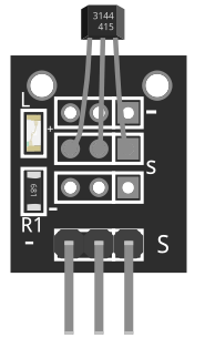
The Keys KY-003 Hall Effect Sensor is a compact and reliable device designed to detect the presence of a magnetic field. It operates based on the Hall effect principle, producing a voltage output proportional to the strength of the magnetic field. This sensor is widely used in applications such as position sensing, speed detection, and current sensing. Its small size and ease of integration make it a popular choice for both hobbyists and professionals.
Explore Projects Built with Sensor de Efecto Hall
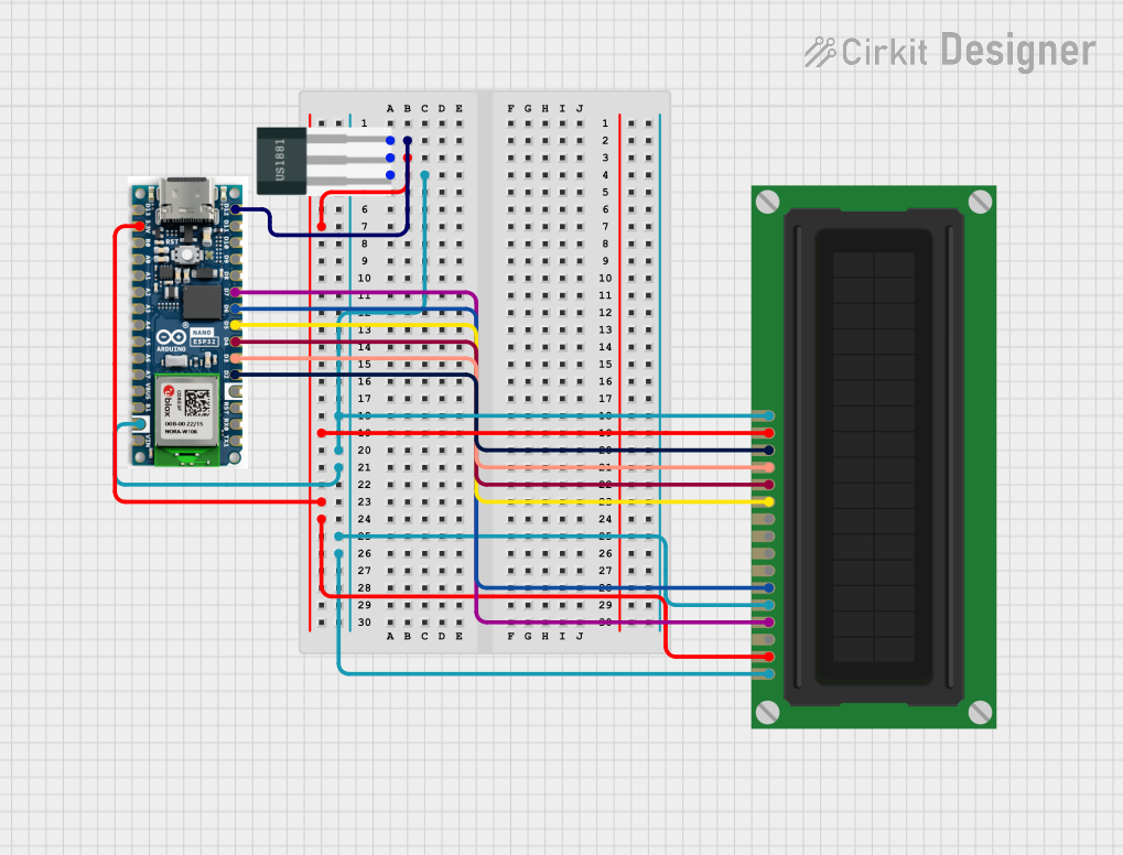

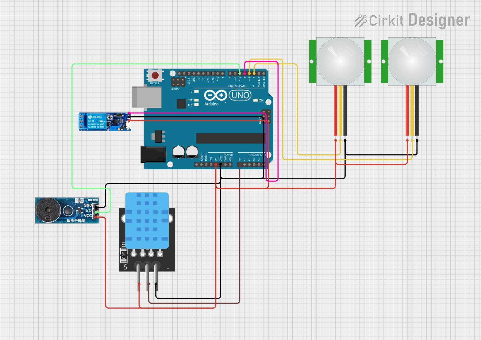
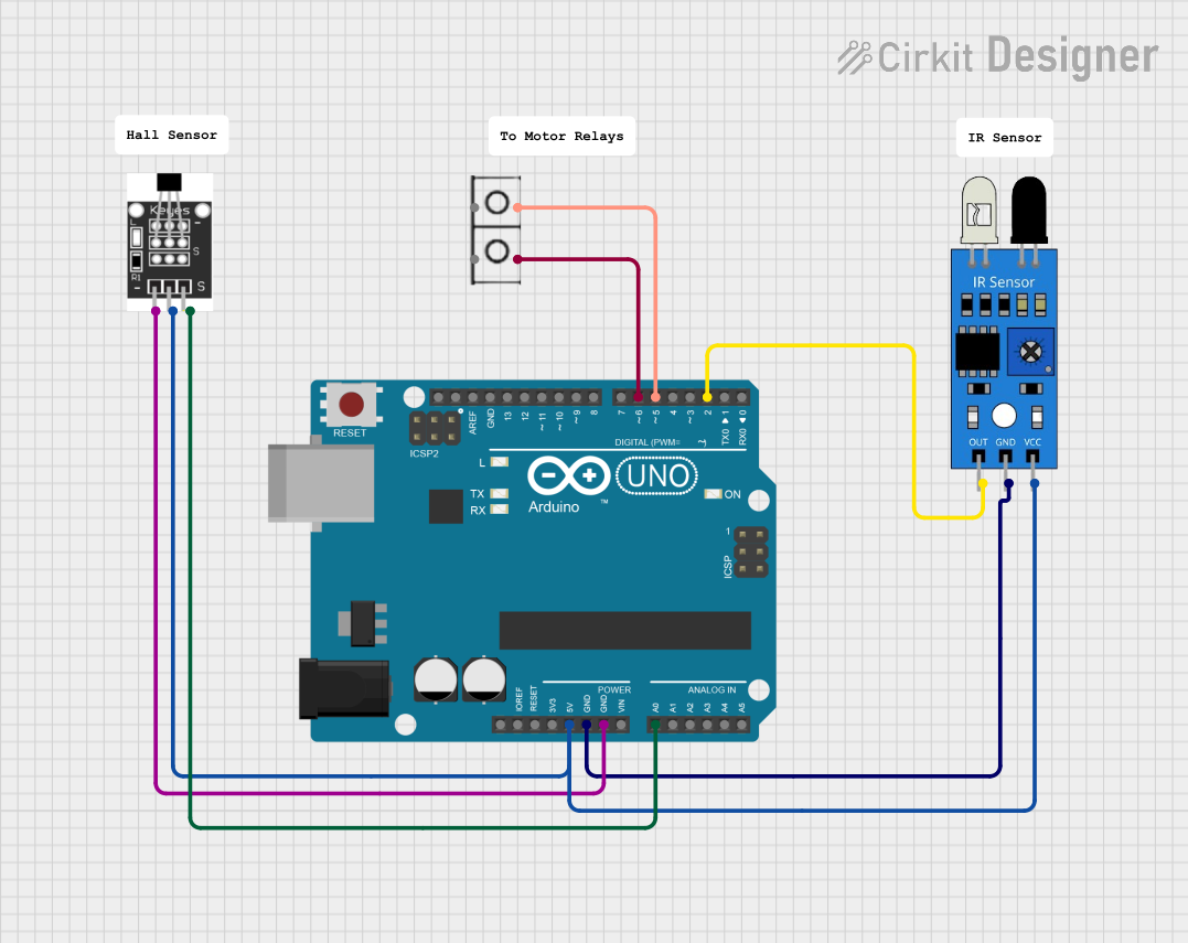
Explore Projects Built with Sensor de Efecto Hall
Common Applications
- Position Sensing: Detecting the position of moving parts in machinery.
- Speed Detection: Measuring the rotational speed of motors or wheels.
- Current Sensing: Monitoring current flow in electrical circuits.
- Proximity Detection: Identifying the presence of magnetic objects.
Technical Specifications
The following table outlines the key technical details of the KY-003 Hall Effect Sensor:
| Parameter | Value |
|---|---|
| Manufacturer | Keys |
| Part ID | KY-003 |
| Operating Voltage | 4.5V to 24V |
| Output Voltage | Digital (High/Low) |
| Output Current | 25mA (maximum) |
| Magnetic Sensitivity | 1.5mT to 3mT |
| Operating Temperature | -40°C to +85°C |
| Dimensions | 18.5mm x 15mm x 7.5mm |
Pin Configuration
The KY-003 sensor has three pins, as described in the table below:
| Pin | Name | Description |
|---|---|---|
| 1 | VCC | Power supply pin (4.5V to 24V) |
| 2 | GND | Ground connection |
| 3 | OUT | Digital output pin (High when magnetic field is detected) |
Usage Instructions
How to Use the KY-003 in a Circuit
- Power the Sensor: Connect the VCC pin to a 5V power source (e.g., Arduino UNO 5V pin) and the GND pin to ground.
- Connect the Output: Attach the OUT pin to a digital input pin on your microcontroller or to an external circuit for signal processing.
- Place a Magnet: Position a magnet near the sensor. The sensor will output a HIGH signal when it detects a magnetic field and a LOW signal when no field is present.
Important Considerations
- Magnetic Field Orientation: Ensure the magnetic field is perpendicular to the sensor for optimal detection.
- Power Supply: Use a stable power source to avoid erratic behavior.
- Pull-up Resistor: If the output signal is unstable, consider adding a pull-up resistor (e.g., 10kΩ) to the OUT pin.
- Distance: The sensor's sensitivity decreases with distance from the magnetic source. Keep the magnet within the specified range.
Example: Connecting to an Arduino UNO
Below is an example of how to use the KY-003 Hall Effect Sensor with an Arduino UNO:
// KY-003 Hall Effect Sensor Example with Arduino UNO
// This code reads the sensor's output and prints the status to the Serial Monitor.

const int sensorPin = 2; // Connect KY-003 OUT pin to Arduino digital pin 2
const int ledPin = 13;   // Built-in LED for visual feedback

void setup() {
  pinMode(sensorPin, INPUT); // Set sensor pin as input
  pinMode(ledPin, OUTPUT);   // Set LED pin as output
  Serial.begin(9600);        // Initialize serial communication
}

void loop() {
  int sensorValue = digitalRead(sensorPin); // Read the sensor's output

  if (sensorValue == HIGH) {
    // Magnetic field detected
    digitalWrite(ledPin, HIGH); // Turn on LED
    Serial.println("Magnetic field detected!");
  } else {
    // No magnetic field
    digitalWrite(ledPin, LOW);  // Turn off LED
    Serial.println("No magnetic field.");
  }

  delay(500); // Wait for 500ms before the next reading
}
Best Practices
- Use a decoupling capacitor (e.g., 0.1µF) between VCC and GND to reduce noise.
- Avoid placing the sensor near strong electromagnetic interference sources.
- Test the sensor with different magnets to determine the optimal sensitivity for your application.
Troubleshooting and FAQs
Common Issues and Solutions
No Output Signal:
- Verify the power supply voltage is within the specified range (4.5V to 24V).
- Check all connections for loose wires or incorrect pin assignments.
- Ensure the magnet is within the sensor's detection range.
Unstable Output:
- Add a pull-up resistor to the OUT pin to stabilize the signal.
- Use a decoupling capacitor to filter out noise from the power supply.
Sensor Not Responding to Magnet:
- Confirm the magnet's orientation and ensure it is perpendicular to the sensor.
- Test with a stronger magnet if the current one is too weak.
Interference from Nearby Devices:
- Relocate the sensor away from sources of electromagnetic interference, such as motors or high-current wires.
FAQs
Q: Can the KY-003 detect both north and south poles of a magnet?
A: Yes, the KY-003 can detect both poles, but it does not differentiate between them. It only detects the presence of a magnetic field.
Q: What is the maximum distance for magnetic field detection?
A: The detection range depends on the strength of the magnet. Typically, the sensor can detect fields within a few millimeters to a few centimeters.
Q: Can I use the KY-003 with a 3.3V microcontroller?
A: While the sensor operates at 4.5V to 24V, you can use a voltage divider or level shifter to safely interface it with a 3.3V microcontroller.
Q: Is the KY-003 suitable for high-speed applications?
A: Yes, the KY-003 has a fast response time, making it suitable for applications like speed detection.
By following this documentation, you can effectively integrate the KY-003 Hall Effect Sensor into your projects and troubleshoot any issues that arise.