
How to Use RELAY SRD-05VDC-SL-C: Examples, Pinouts, and Specs
 Design with RELAY SRD-05VDC-SL-C in Cirkit Designer
Introduction
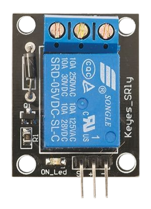
The RELAY SRD-05VDC-SL-C is a 5V DC relay module designed for switching high-voltage devices using low-voltage control signals. It features a Single Pole Double Throw (SPDT) configuration, enabling it to control multiple circuits. This relay is widely used in automation, home appliances, and DIY electronics projects due to its reliability and ease of use.
Explore Projects Built with RELAY SRD-05VDC-SL-C
 Open Project in Cirkit Designer
 Open Project in Cirkit Designer
 Open Project in Cirkit Designer
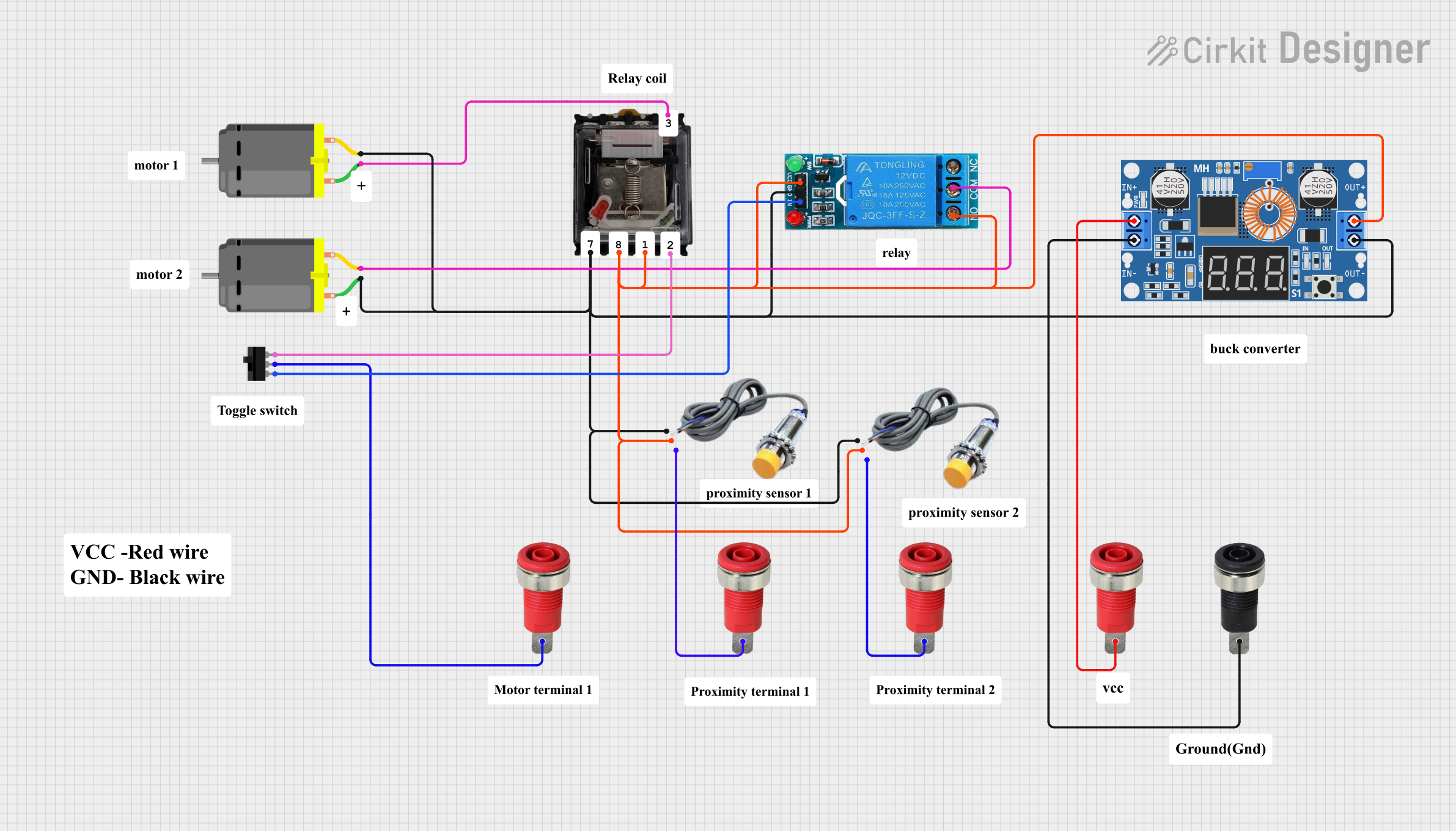 Open Project in Cirkit Designer
Explore Projects Built with RELAY SRD-05VDC-SL-C
Open Project in Cirkit DesignerOpen Project in Cirkit DesignerOpen Project in Cirkit DesignerOpen Project in Cirkit DesignerCommon Applications and Use Cases
- Home automation systems (e.g., controlling lights, fans, or appliances)
- Industrial control systems
- DIY electronics projects
- Robotics and IoT applications
- Switching high-power devices like motors or heaters
Technical Specifications
Below are the key technical details and pin configuration for the RELAY SRD-05VDC-SL-C:
Key Technical Details
| Parameter | Value |
|---|---|
| Operating Voltage | 5V DC |
| Trigger Voltage | 3.75V to 5V DC |
| Trigger Current | 15-20 mA |
| Contact Type | SPDT (Single Pole Double Throw) |
| Maximum Switching Voltage | 250V AC / 30V DC |
| Maximum Switching Current | 10A |
| Coil Resistance | ~70Ω |
| Isolation | Optocoupler isolation (if part of a module) |
| Dimensions | 19mm x 15.5mm x 15mm |
Pin Configuration and Descriptions
The RELAY SRD-05VDC-SL-C typically has 5 pins when used as part of a relay module. Below is the pin configuration:
Control Side (Low Voltage)
| Pin Name | Description |
|---|---|
| VCC | Connect to 5V DC power supply |
| GND | Connect to ground |
| IN | Control signal input (HIGH to activate relay) |
Load Side (High Voltage)
| Pin Name | Description |
|---|---|
| COM | Common terminal for the load circuit |
| NO | Normally Open terminal (connected to COM when relay is activated) |
| NC | Normally Closed terminal (connected to COM when relay is inactive) |
Usage Instructions
How to Use the Component in a Circuit
- Power the Relay Module: Connect the VCC pin to a 5V DC power supply and the GND pin to ground.
- Control Signal: Connect the IN pin to a microcontroller (e.g., Arduino) or any other control circuit. A HIGH signal (typically 5V) will activate the relay.
- Load Connection:
- Connect the high-voltage device's live wire to the COM terminal.
- Use the NO terminal if you want the device to turn ON when the relay is activated.
- Use the NC terminal if you want the device to turn OFF when the relay is activated.
- Isolation: If the relay module includes an optocoupler, it provides electrical isolation between the control and load sides, enhancing safety.
Important Considerations and Best Practices
- Current Ratings: Ensure the load does not exceed the relay's maximum current rating (10A).
- Flyback Diode: If you're using the relay without a module, add a flyback diode across the relay coil to protect the control circuit from voltage spikes.
- Power Supply: Use a stable 5V DC power supply to avoid erratic relay behavior.
- Safety: Always handle high-voltage connections with care. Disconnect power before wiring.
Example Code for Arduino UNO
Below is an example of how to control the RELAY SRD-05VDC-SL-C with an Arduino UNO:
// Define the relay control pin
const int relayPin = 7; // Connect the IN pin of the relay to pin 7 on Arduino

void setup() {
  pinMode(relayPin, OUTPUT); // Set the relay pin as an output
  digitalWrite(relayPin, LOW); // Ensure the relay is off initially
}

void loop() {
  digitalWrite(relayPin, HIGH); // Turn the relay ON
  delay(5000); // Keep the relay ON for 5 seconds
  digitalWrite(relayPin, LOW); // Turn the relay OFF
  delay(5000); // Keep the relay OFF for 5 seconds
}
Code Explanation:
- The
relayPinis set to pin 7 on the Arduino. - The
setup()function initializes the relay pin as an output and ensures the relay is OFF initially. - The
loop()function alternates between turning the relay ON and OFF every 5 seconds.
Troubleshooting and FAQs
Common Issues and Solutions
Relay Not Activating:
- Cause: Insufficient control signal voltage.
- Solution: Ensure the control signal voltage is between 3.75V and 5V.
Relay Clicking Rapidly:
- Cause: Unstable power supply or noisy control signal.
- Solution: Use a decoupling capacitor near the relay module's VCC and GND pins.
Load Not Switching:
- Cause: Incorrect wiring of the load circuit.
- Solution: Double-check the connections to the COM, NO, and NC terminals.
Arduino Resets When Relay Activates:
- Cause: Voltage spikes or insufficient power supply.
- Solution: Add a flyback diode across the relay coil and ensure the Arduino has a stable power source.
FAQs
Q1: Can I use the RELAY SRD-05VDC-SL-C with a 3.3V microcontroller?
A1: Yes, but you may need a transistor or MOSFET to amplify the control signal to 5V.
Q2: Is the relay safe for switching AC loads?
A2: Yes, it can switch AC loads up to 250V, but ensure proper insulation and safety precautions.
Q3: Can I control multiple relays with one Arduino?
A3: Yes, as long as each relay has its own control pin and the Arduino can supply sufficient current.
Q4: What is the lifespan of the relay?
A4: The relay is rated for approximately 100,000 mechanical operations under normal conditions.