How to Use JST PH-2 2-Pin Male Housing: Examples, Pinouts, and Specs
Introduction
The JST PH-2 2-Pin Male Housing is a compact and reliable connector housing designed for 2-pin electrical connections. It is part of the JST PH series, known for its small size and secure locking mechanism. This connector is widely used in electronic devices, including battery packs, sensors, and small appliances, where space-saving and dependable connections are essential.
Explore Projects Built with JST PH-2 2-Pin Male Housing
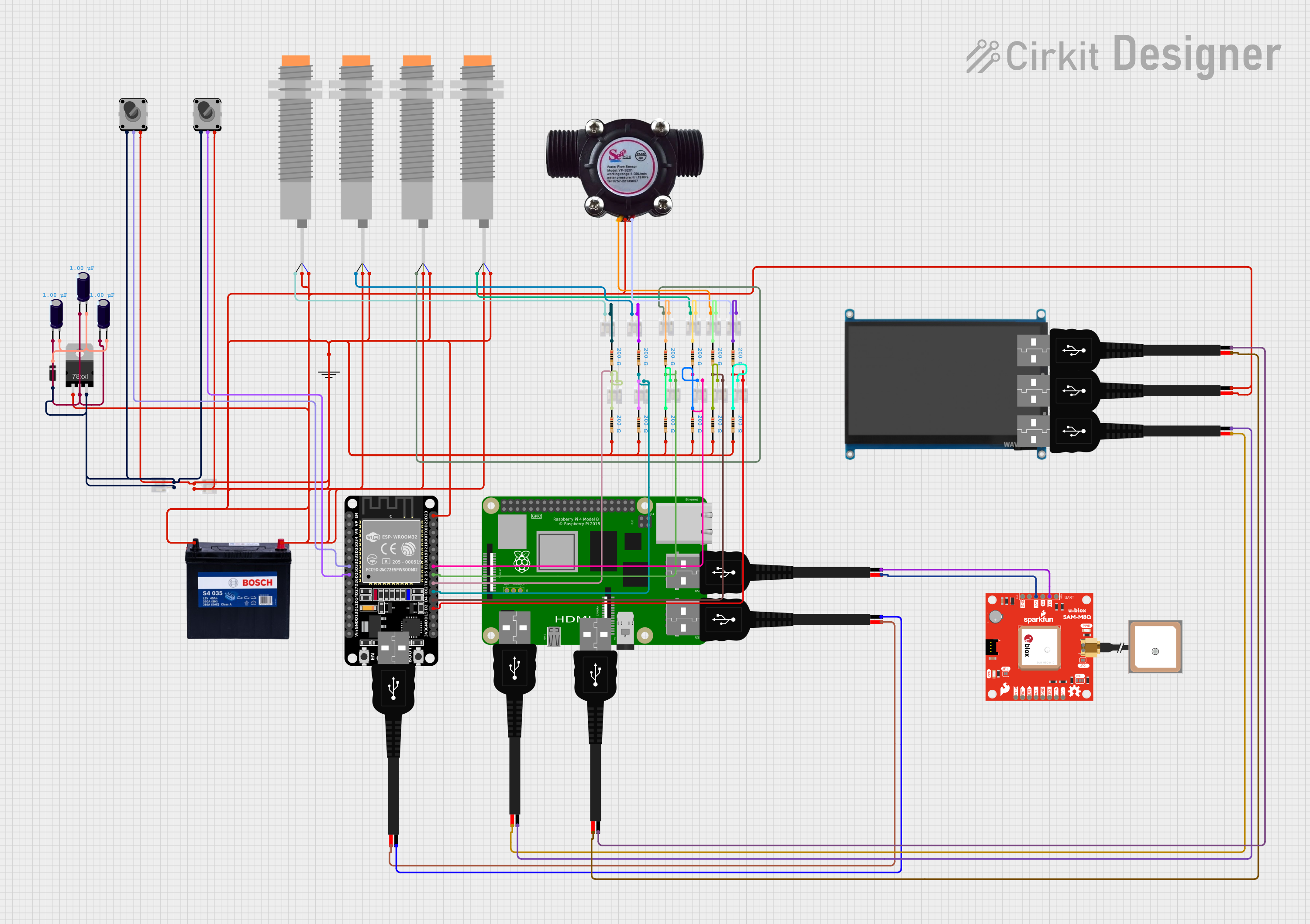


Explore Projects Built with JST PH-2 2-Pin Male Housing
Common Applications and Use Cases
- Connecting battery packs to circuit boards
- Interfacing sensors and modules in compact devices
- Power delivery in small electronic appliances
- Robotics and hobbyist projects requiring secure connections
Technical Specifications
The JST PH-2 2-Pin Male Housing is designed to work with compatible crimp terminals and female connectors. Below are its key technical details:
Key Specifications
| Parameter | Value |
|---|---|
| Number of Pins | 2 |
| Pitch (Pin Spacing) | 2.0 mm |
| Current Rating | 2 A (maximum) |
| Voltage Rating | 100 V AC/DC (maximum) |
| Operating Temperature | -25°C to +85°C |
| Housing Material | Nylon 66 (UL94V-0 rated) |
| Locking Mechanism | Friction lock |
Pin Configuration and Descriptions
The JST PH-2 2-Pin Male Housing does not have specific pin numbering, as it is a passive housing. However, the two pins are typically used as follows:
| Pin Number | Typical Use |
|---|---|
| 1 | Positive (+) |
| 2 | Negative (-) or GND |
Note: Ensure proper polarity when connecting to avoid damage to your circuit.
Usage Instructions
How to Use the JST PH-2 2-Pin Male Housing in a Circuit
Prepare the Wires:
- Strip approximately 2-3 mm of insulation from the ends of the wires you intend to connect.
- Use wires with a gauge compatible with the crimp terminals (typically 28-22 AWG).
Crimp the Terminals:
- Insert the stripped wire into the crimp terminal.
- Use a crimping tool designed for JST PH terminals to securely crimp the wire and terminal.
Insert Terminals into the Housing:
- Align the crimped terminals with the slots in the JST PH-2 housing.
- Push the terminals into the housing until they click into place.
Connect to the Female Connector:
- Align the male housing with the corresponding JST PH-2 female connector.
- Push the connectors together until the friction lock engages.
Important Considerations and Best Practices
- Polarity: Always double-check the polarity of your connections to prevent damage to your components.
- Wire Gauge: Use wires within the recommended gauge range to ensure a secure crimp and reliable connection.
- Crimping Tool: Use a proper crimping tool for JST PH terminals to avoid loose or unreliable connections.
- Insertion Force: Do not force the terminals into the housing; ensure they are properly aligned.
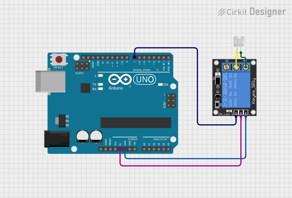
Example: Connecting to an Arduino UNO
The JST PH-2 connector is often used to connect battery packs or sensors to an Arduino UNO. Below is an example of how to use it with a 3.7V LiPo battery:
// Example: Reading battery voltage using an Arduino UNO
// Ensure the JST PH-2 connector is wired correctly to the battery and Arduino.

const int batteryPin = A0; // Analog pin connected to the battery's positive terminal
float batteryVoltage = 0.0;

void setup() {
  Serial.begin(9600); // Initialize serial communication
}

void loop() {
  int sensorValue = analogRead(batteryPin); // Read the analog value
  batteryVoltage = sensorValue * (5.0 / 1023.0); // Convert to voltage
  Serial.print("Battery Voltage: ");
  Serial.println(batteryVoltage); // Print the voltage to the Serial Monitor
  delay(1000); // Wait for 1 second
}
Note: Use a voltage divider if the battery voltage exceeds the Arduino's input voltage range.
Troubleshooting and FAQs
Common Issues and Solutions
Terminals Not Locking into the Housing:
- Cause: Terminals may not be fully crimped or aligned.
- Solution: Ensure the crimping process is done correctly and the terminals are properly aligned with the housing slots.
Loose Connection:
- Cause: Incorrect wire gauge or improper crimping.
- Solution: Use wires within the recommended gauge range and ensure a secure crimp with the correct tool.
Connector Does Not Fit:
- Cause: Using an incompatible female connector.
- Solution: Verify that the female connector is part of the JST PH series and matches the 2.0 mm pitch.
Polarity Reversed:
- Cause: Wires connected to the wrong pins.
- Solution: Double-check the polarity before connecting to the circuit.
FAQs
Q: Can I reuse the JST PH-2 housing?
A: Yes, the housing can be reused, but the crimp terminals may need to be replaced if they are damaged during removal.
Q: What is the maximum wire length I can use with this connector?
A: There is no specific limit, but longer wires may introduce resistance and voltage drop. Use appropriate wire gauges for longer distances.
Q: Is the JST PH-2 connector waterproof?
A: No, the JST PH-2 connector is not waterproof. For outdoor or moisture-prone applications, consider using waterproof connectors.
Q: Can I solder wires directly to the housing?
A: No, the housing is designed for use with crimp terminals. Soldering directly to the housing is not recommended and may damage it.