How to Use scan_brd: Examples, Pinouts, and Specs
Introduction
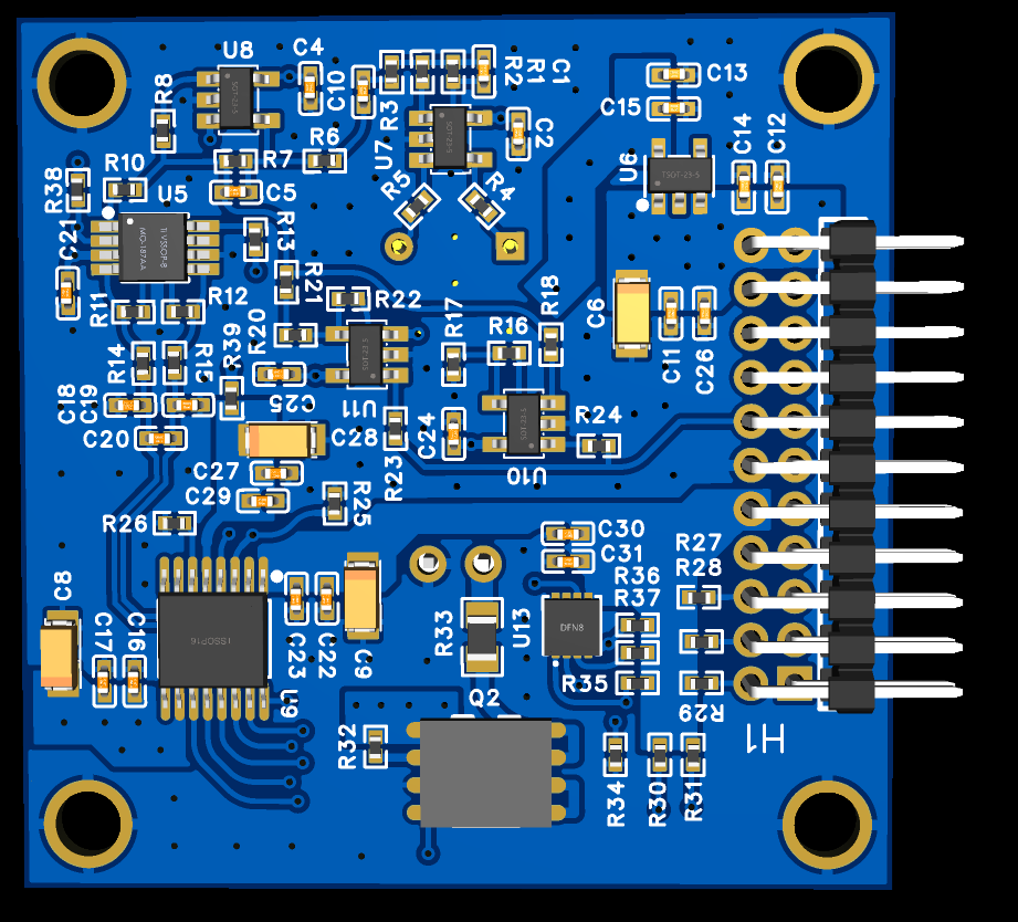
The scan_brd (Manufacturer Part ID: Brd_v1) by Pime is a versatile circuit board designed for testing and debugging electronic circuits. It is equipped with multiple test points, signal interfaces, and diagnostic features to facilitate the analysis of signal integrity, performance, and functionality in electronic systems. The scan_brd is an essential tool for engineers and technicians working on prototyping, troubleshooting, and validating circuit designs.
Explore Projects Built with scan_brd

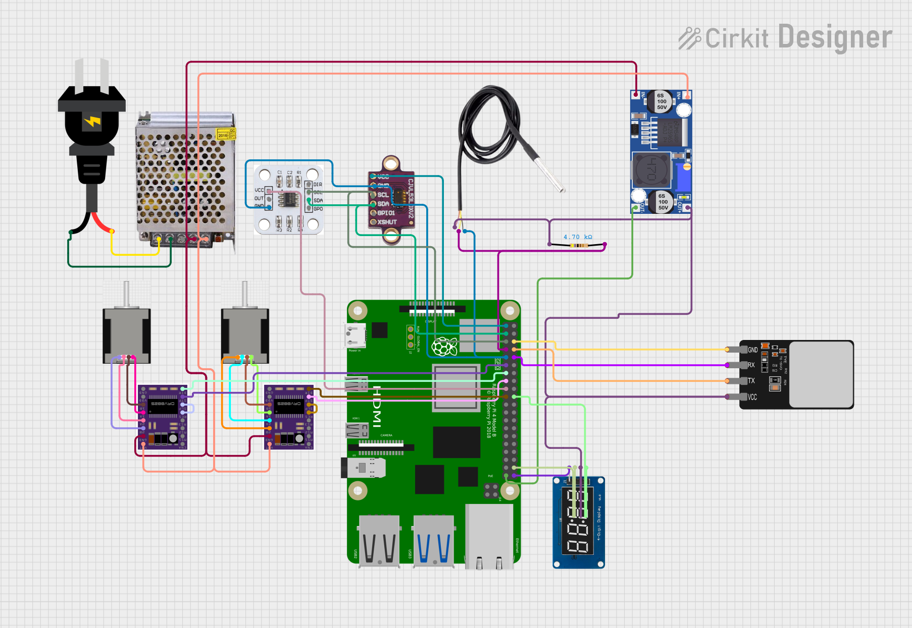
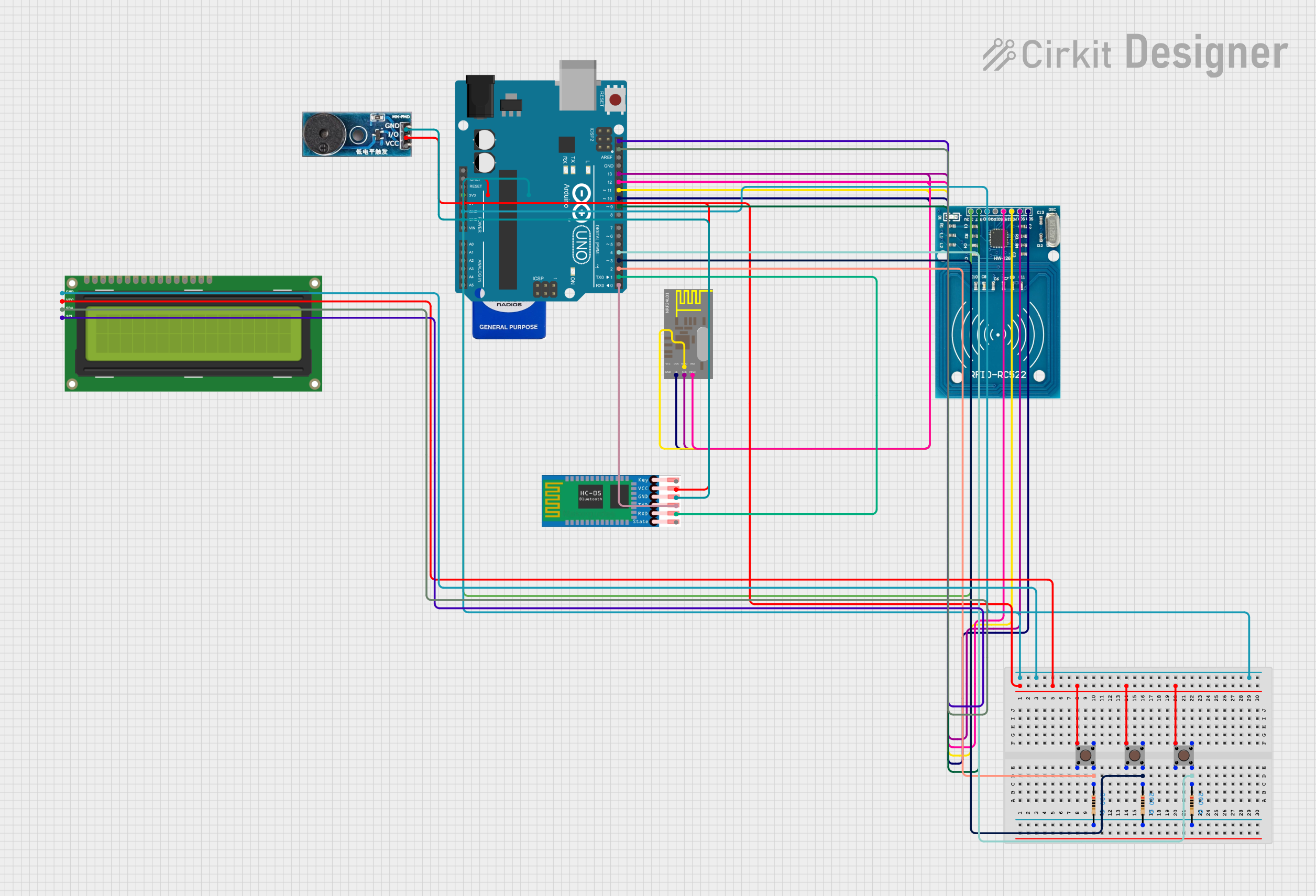
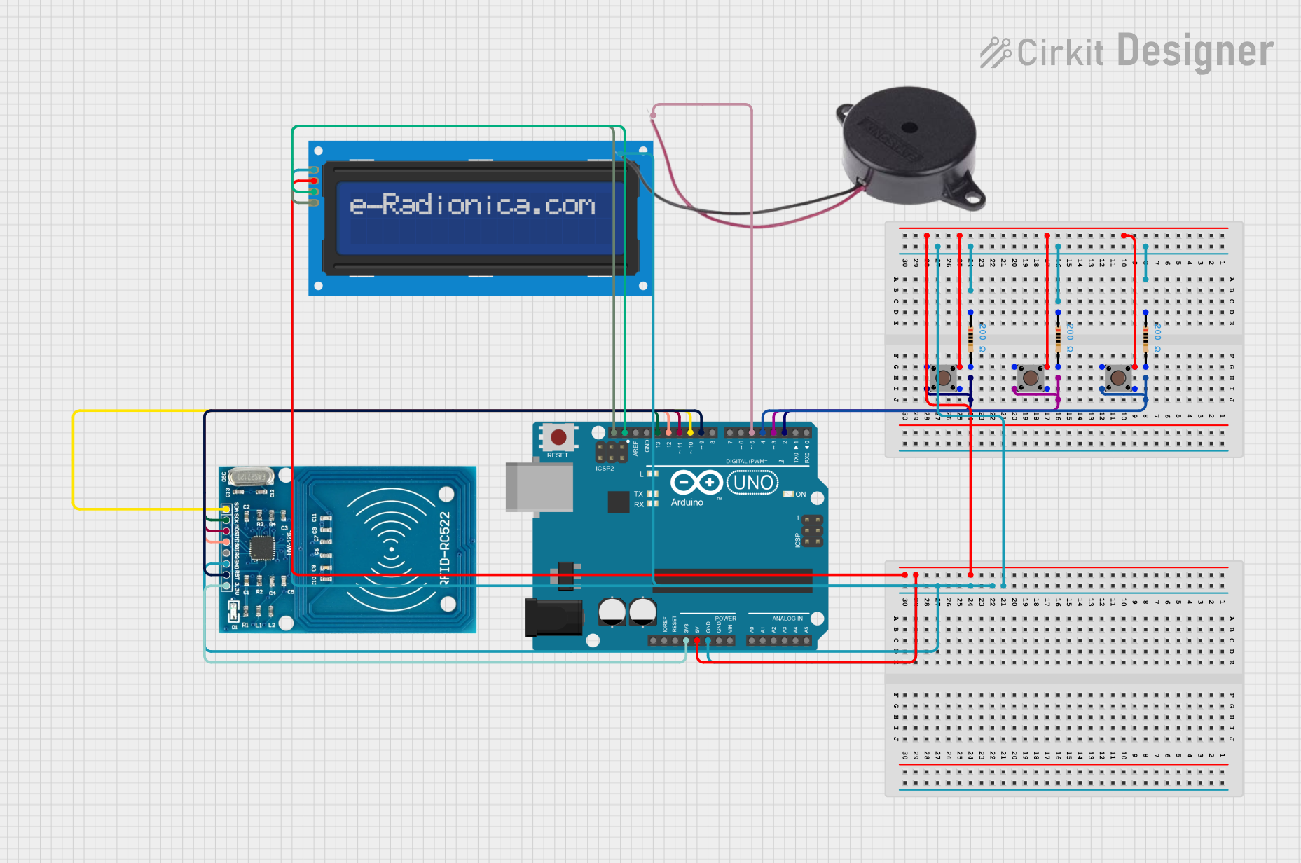
Explore Projects Built with scan_brd
Common Applications and Use Cases
- Debugging and testing electronic circuits during development.
- Signal integrity analysis in high-speed digital systems.
- Prototyping and validating new circuit designs.
- Educational purposes for learning circuit testing techniques.
- Integration with microcontrollers and development boards for advanced diagnostics.
Technical Specifications
The scan_brd is designed to provide robust testing capabilities with the following specifications:
Key Technical Details
| Parameter | Specification |
|---|---|
| Operating Voltage | 3.3V to 5V |
| Maximum Current | 500mA |
| Supported Interfaces | GPIO, I2C, SPI, UART |
| Test Points | 20 labeled test points |
| Dimensions | 80mm x 60mm x 1.6mm |
| PCB Material | FR4, 2-layer |
| Connector Type | Standard 0.1-inch (2.54mm) headers |
| Operating Temperature | -20°C to 70°C |
Pin Configuration and Descriptions
The scan_brd features a 20-pin header for interfacing with external devices. The pin configuration is as follows:
| Pin Number | Label | Description |
|---|---|---|
| 1 | VCC | Power supply input (3.3V to 5V) |
| 2 | GND | Ground |
| 3 | TX | UART Transmit |
| 4 | RX | UART Receive |
| 5 | SCL | I2C Clock Line |
| 6 | SDA | I2C Data Line |
| 7 | MISO | SPI Master In, Slave Out |
| 8 | MOSI | SPI Master Out, Slave In |
| 9 | SCK | SPI Clock |
| 10 | CS | SPI Chip Select |
| 11-20 | TP1-TP10 | General-purpose test points |
Usage Instructions
The scan_brd is straightforward to use and can be integrated into various testing setups. Follow these steps to use the component effectively:
How to Use the Component in a Circuit
- Power the Board: Connect the VCC and GND pins to a regulated power supply (3.3V or 5V).
- Connect to a Device Under Test (DUT): Use the labeled test points (TP1-TP10) to probe signals from the DUT.
- Interface with Microcontrollers: Connect the UART, I2C, or SPI pins to a microcontroller or development board for advanced diagnostics.
- Monitor Signals: Use an oscilloscope or logic analyzer to monitor signals at the test points.
Important Considerations and Best Practices
- Ensure the power supply voltage matches the operating voltage of the scan_brd (3.3V or 5V).
- Avoid exceeding the maximum current rating of 500mA to prevent damage.
- Use short, high-quality wires to minimize noise and signal degradation.
- When using the board with an Arduino UNO, ensure proper pin mapping for UART, I2C, or SPI communication.
Example: Using scan_brd with Arduino UNO
Below is an example of using the scan_brd to read data from an I2C device connected to the board:
#include <Wire.h> // Include the Wire library for I2C communication

#define I2C_ADDRESS 0x3C // Replace with the I2C address of your device

void setup() {
  Wire.begin(); // Initialize I2C communication
  Serial.begin(9600); // Start serial communication for debugging
  Serial.println("scan_brd I2C Test Initialized");
}

void loop() {
  Wire.beginTransmission(I2C_ADDRESS); // Start communication with the I2C device
  Wire.write(0x00); // Send a command or register address (example: 0x00)
  Wire.endTransmission();

  Wire.requestFrom(I2C_ADDRESS, 1); // Request 1 byte of data from the device
  if (Wire.available()) {
    int data = Wire.read(); // Read the received data
    Serial.print("Received Data: ");
    Serial.println(data);
  }

  delay(1000); // Wait for 1 second before the next read
}
Troubleshooting and FAQs
Common Issues Users Might Face
No Power to the Board:
- Cause: Incorrect voltage or loose connections.
- Solution: Verify the power supply voltage (3.3V or 5V) and check all connections.
Signal Noise or Interference:
- Cause: Long wires or poor grounding.
- Solution: Use short, shielded wires and ensure a solid ground connection.
I2C/SPI Communication Fails:
- Cause: Incorrect pin connections or mismatched settings.
- Solution: Double-check the pin connections and ensure the communication settings (e.g., clock speed) match the device specifications.
Test Points Not Responding:
- Cause: Faulty probes or incorrect connections.
- Solution: Inspect the probes and ensure they are securely connected to the test points.
Solutions and Tips for Troubleshooting
- Use a multimeter to verify voltage levels at the VCC and GND pins.
- Check for continuity between the test points and the DUT to ensure proper connections.
- If using the board with a microcontroller, confirm that the firmware is correctly configured for the desired interface (UART, I2C, or SPI).
By following this documentation, users can effectively utilize the scan_brd for testing and debugging electronic circuits.