How to Use SSR-10A: Examples, Pinouts, and Specs
Introduction
The SSR-10A is a solid-state relay (SSR) designed for switching AC loads. Unlike traditional mechanical relays, the SSR-10A uses semiconductor components to perform switching operations, ensuring faster response times, longer lifespan, and silent operation. It provides electrical isolation between the control circuit and the load circuit, making it a safe and reliable choice for various applications.
Explore Projects Built with SSR-10A


Explore Projects Built with SSR-10A
Common Applications and Use Cases
- Industrial automation systems
- Heating, ventilation, and air conditioning (HVAC) systems
- Motor control and lighting systems
- Home automation projects
- High-power device switching in Arduino or microcontroller-based projects
Technical Specifications
The SSR-10A is designed to handle medium-power AC loads with high efficiency and reliability. Below are its key technical details:
| Parameter | Value |
|---|---|
| Load Voltage Range | 24V AC to 380V AC |
| Load Current Rating | 10A |
| Control Voltage Range | 3V DC to 32V DC |
| Control Current | ≤12mA |
| Isolation Voltage | ≥2500V AC |
| On-State Voltage Drop | ≤1.6V |
| Switching Time | ≤10ms |
| Operating Temperature | -30°C to +75°C |
| Mounting Type | Panel-mounted |
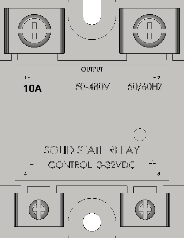
Pin Configuration and Descriptions
The SSR-10A has four terminals, as described in the table below:
| Pin | Label | Description |
|---|---|---|
| 1 | Input (+) | Positive terminal for the control signal (3V DC to 32V DC). |
| 2 | Input (-) | Negative terminal for the control signal (ground). |
| 3 | Load (AC1) | One terminal of the AC load circuit. Connect to the live or neutral wire. |
| 4 | Load (AC2) | The other terminal of the AC load circuit. Connect to the remaining live/neutral. |
Usage Instructions
How to Use the SSR-10A in a Circuit
Control Circuit Connection:
- Connect the positive control signal (e.g., from a microcontroller or Arduino) to the
Input (+)terminal. - Connect the ground of the control signal to the
Input (-)terminal. - Ensure the control voltage is within the range of 3V DC to 32V DC.
- Connect the positive control signal (e.g., from a microcontroller or Arduino) to the
Load Circuit Connection:
- Connect the AC load (e.g., a motor, light, or heater) to the
Load (AC1)andLoad (AC2)terminals. - Ensure the load voltage is within the range of 24V AC to 380V AC and does not exceed the 10A current rating.
- Connect the AC load (e.g., a motor, light, or heater) to the
Power Supply:
- Ensure the control circuit and load circuit are powered separately to maintain electrical isolation.
Mounting:
- Secure the SSR-10A to a heat sink or metal surface if operating near its maximum current rating to prevent overheating.
Important Considerations and Best Practices
- Heat Dissipation: Use a heat sink or cooling fan if the relay operates at high currents for extended periods.
- Snubber Circuit: For inductive loads (e.g., motors), use a snubber circuit to suppress voltage spikes and protect the SSR.
- Control Signal Voltage: Ensure the control signal voltage is stable and within the specified range to avoid malfunction.
- Load Compatibility: Verify that the load's voltage and current ratings are within the SSR-10A's specifications.
Example: Using SSR-10A with Arduino UNO
Below is an example of how to control an AC load using the SSR-10A and an Arduino UNO:
// Example: Controlling an AC load with SSR-10A and Arduino UNO
// Pin 9 is used to control the SSR-10A

const int ssrPin = 9; // Define the pin connected to the SSR-10A control input

void setup() {
  pinMode(ssrPin, OUTPUT); // Set the SSR pin as an output
}

void loop() {
  digitalWrite(ssrPin, HIGH); // Turn on the AC load
  delay(5000);                // Keep the load on for 5 seconds
  digitalWrite(ssrPin, LOW);  // Turn off the AC load
  delay(5000);                // Keep the load off for 5 seconds
}
Note: Ensure proper isolation and safety precautions when working with AC loads.
Troubleshooting and FAQs
Common Issues and Solutions
The SSR does not switch the load on/off:
- Verify that the control voltage is within the range of 3V DC to 32V DC.
- Check the wiring of the control and load circuits for loose or incorrect connections.
- Ensure the load voltage and current are within the SSR-10A's specifications.
Excessive heating of the SSR:
- Ensure the SSR is mounted on a heat sink or metal surface for proper heat dissipation.
- Check if the load current exceeds the 10A rating.
Load flickering or unstable operation:
- Verify that the control signal is stable and not fluctuating.
- For inductive loads, use a snubber circuit to suppress voltage spikes.
No isolation between control and load circuits:
- Ensure proper wiring and avoid connecting the control circuit ground to the load circuit.
FAQs
Q1: Can the SSR-10A be used with DC loads?
No, the SSR-10A is designed specifically for AC loads. For DC loads, use a DC-specific solid-state relay.
Q2: Is the SSR-10A polarity-sensitive on the control side?
Yes, the control input terminals (Input (+) and Input (-)) are polarity-sensitive. Ensure correct polarity when connecting the control signal.
Q3: Can I use the SSR-10A without a heat sink?
For low-current applications, a heat sink may not be necessary. However, for currents near the 10A limit, a heat sink is strongly recommended to prevent overheating.
Q4: What happens if the load exceeds 10A?
Exceeding the 10A rating can damage the SSR-10A permanently. Always ensure the load current is within the specified limit.