Cirkit Designer Logo
Cirkit Designer
Your all-in-one circuit design IDE
Home / 
Component Documentation

How to Use Water Flow Rate Sensor YF-S401: Examples, Pinouts, and Specs

Image of Water Flow Rate Sensor YF-S401
Cirkit Designer LogoDesign with Water Flow Rate Sensor YF-S401 in Cirkit Designer

Introduction

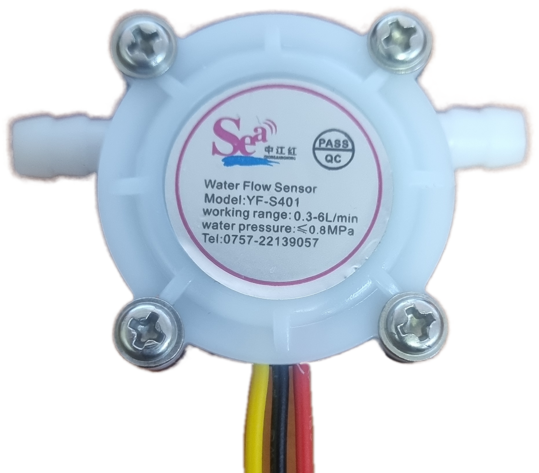
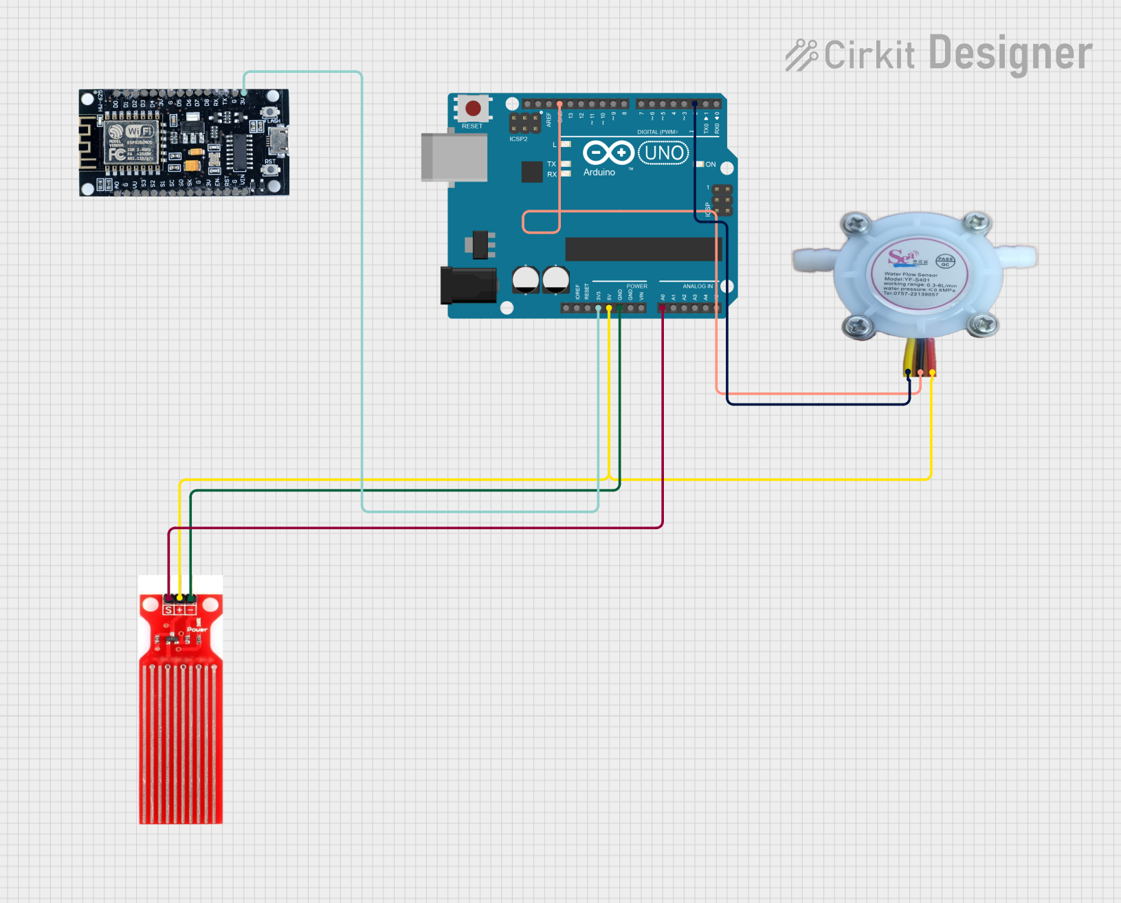
The Water Flow Rate Sensor YF-S401 by Sea is a compact and versatile sensor designed to measure the flow rate of water. It is commonly used in applications such as irrigation systems, water dispensers, and in any system where monitoring water consumption or flow is necessary. The sensor operates by detecting the movement of water through a pipe and converting it into a measurable signal.

Explore Projects Built with Water Flow Rate Sensor YF-S401

Use Cirkit Designer to design, explore, and prototype these projects online. Some projects support real-time simulation. Click "Open Project" to start designing instantly!
Arduino UNO Water Flow Rate Monitor with YF-S401 Sensor
Image of flow rate sensor: A project utilizing Water Flow Rate Sensor YF-S401 in a practical application
This circuit uses an Arduino UNO to read the water flow rate from a YF-S401 water flow rate sensor. The sensor is powered by the Arduino's 5V and GND pins, and its output signal is read by the Arduino's analog pin A0. The Arduino processes this signal to calculate and display the flow rate in liters per minute on the Serial Monitor.
Cirkit Designer LogoOpen Project in Cirkit Designer
ESP32 Wi-Fi Connected Water Flow Meter with Battery Power
Image of phil: A project utilizing Water Flow Rate Sensor YF-S401 in a practical application
This circuit features an ESP32 microcontroller connected to a Water Flow Rate Sensor YF-S401 and powered by a 2000mAh battery. The ESP32 reads the water flow data from the sensor, calculates the water volume consumed, and provides this information via a web server over WiFi.
Cirkit Designer LogoOpen Project in Cirkit Designer
Arduino-Based Water Quality Monitoring System with SIM900A and Multiple Sensors
Image of feito: A project utilizing Water Flow Rate Sensor YF-S401 in a practical application
This circuit is a water quality monitoring system that uses an Arduino UNO to collect data from a YF-S201 water flow meter, a turbidity sensor, and a temperature sensor. The collected data is then transmitted via a SIM900A GSM module to a remote server or user through SMS. The system measures water flow rate, temperature, and turbidity, and sends periodic updates.
Cirkit Designer LogoOpen Project in Cirkit Designer
Arduino and ESP8266-Based Water Monitoring System with Flow Rate Sensor
Image of Arduino Uno (RP): A project utilizing Water Flow Rate Sensor YF-S401 in a practical application
This circuit monitors water presence and flow rate using a water sensor and a YF-S401 water flow rate sensor, respectively. The Arduino UNO reads the water sensor's analog signal and the flow rate sensor's pulse output, while the ESP8266 is powered but not actively used in this configuration. The Arduino processes and outputs the sensor data via serial communication for monitoring purposes.
Cirkit Designer LogoOpen Project in Cirkit Designer

Explore Projects Built with Water Flow Rate Sensor YF-S401

Use Cirkit Designer to design, explore, and prototype these projects online. Some projects support real-time simulation. Click "Open Project" to start designing instantly!
Image of flow rate sensor: A project utilizing Water Flow Rate Sensor YF-S401 in a practical application
Arduino UNO Water Flow Rate Monitor with YF-S401 Sensor
This circuit uses an Arduino UNO to read the water flow rate from a YF-S401 water flow rate sensor. The sensor is powered by the Arduino's 5V and GND pins, and its output signal is read by the Arduino's analog pin A0. The Arduino processes this signal to calculate and display the flow rate in liters per minute on the Serial Monitor.
Cirkit Designer LogoOpen Project in Cirkit Designer
Image of phil: A project utilizing Water Flow Rate Sensor YF-S401 in a practical application
ESP32 Wi-Fi Connected Water Flow Meter with Battery Power
This circuit features an ESP32 microcontroller connected to a Water Flow Rate Sensor YF-S401 and powered by a 2000mAh battery. The ESP32 reads the water flow data from the sensor, calculates the water volume consumed, and provides this information via a web server over WiFi.
Cirkit Designer LogoOpen Project in Cirkit Designer
Image of feito: A project utilizing Water Flow Rate Sensor YF-S401 in a practical application
Arduino-Based Water Quality Monitoring System with SIM900A and Multiple Sensors
This circuit is a water quality monitoring system that uses an Arduino UNO to collect data from a YF-S201 water flow meter, a turbidity sensor, and a temperature sensor. The collected data is then transmitted via a SIM900A GSM module to a remote server or user through SMS. The system measures water flow rate, temperature, and turbidity, and sends periodic updates.
Cirkit Designer LogoOpen Project in Cirkit Designer
Image of Arduino Uno (RP): A project utilizing Water Flow Rate Sensor YF-S401 in a practical application
Arduino and ESP8266-Based Water Monitoring System with Flow Rate Sensor
This circuit monitors water presence and flow rate using a water sensor and a YF-S401 water flow rate sensor, respectively. The Arduino UNO reads the water sensor's analog signal and the flow rate sensor's pulse output, while the ESP8266 is powered but not actively used in this configuration. The Arduino processes and outputs the sensor data via serial communication for monitoring purposes.
Cirkit Designer LogoOpen Project in Cirkit Designer

Technical Specifications

Key Technical Details

  • Operating Voltage: 5-18V DC
  • Max Current: 15mA (at 5V)
  • Flow Rate Range: 0.3-6L/min
  • Operating Temperature Range: -25 to +80°C
  • Output Pulse High Level: >4.5V (input voltage 5V)
  • Output Pulse Low Level: <0.5V (input voltage 5V)
  • Accuracy: ±5%
  • Output Duty Cycle: 50% ±10%
  • Output Rise Time: 0.04μs

Pin Configuration and Descriptions

Pin Number Description Notes
1 GND (Ground) Connect to system ground
2 VCC (Power Supply) 5-18V DC
3 Signal Output Outputs pulse signal

Usage Instructions

Integration into a Circuit

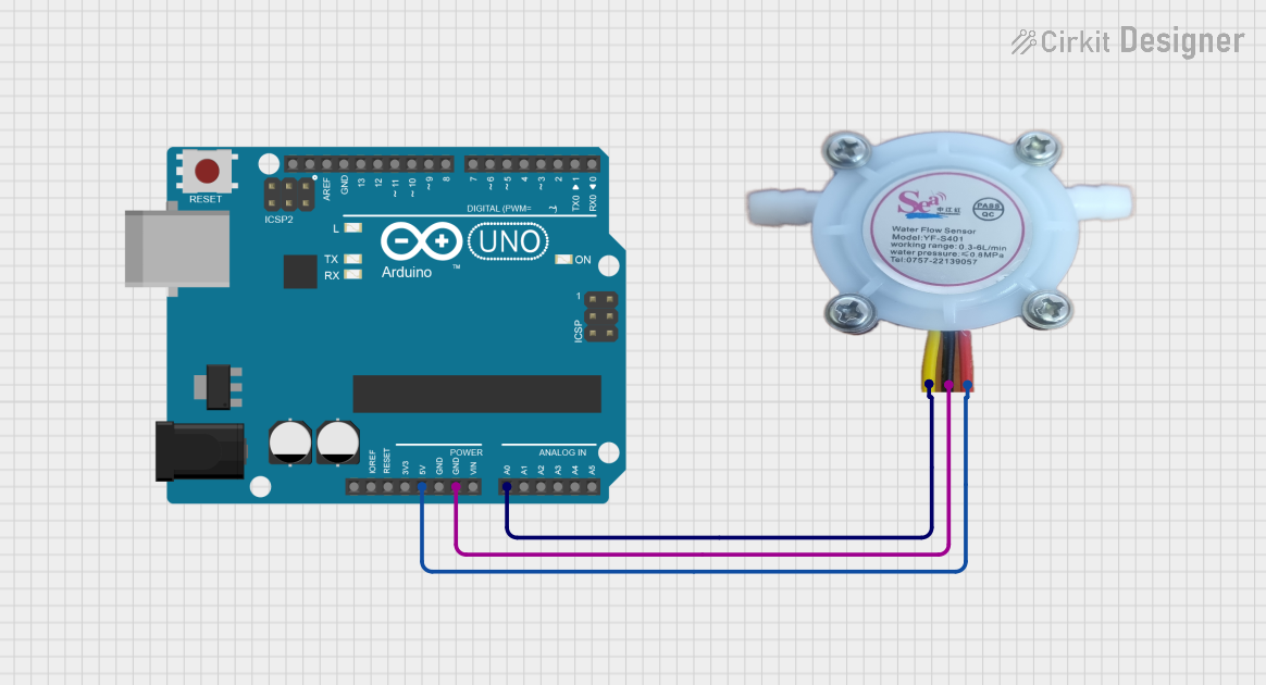
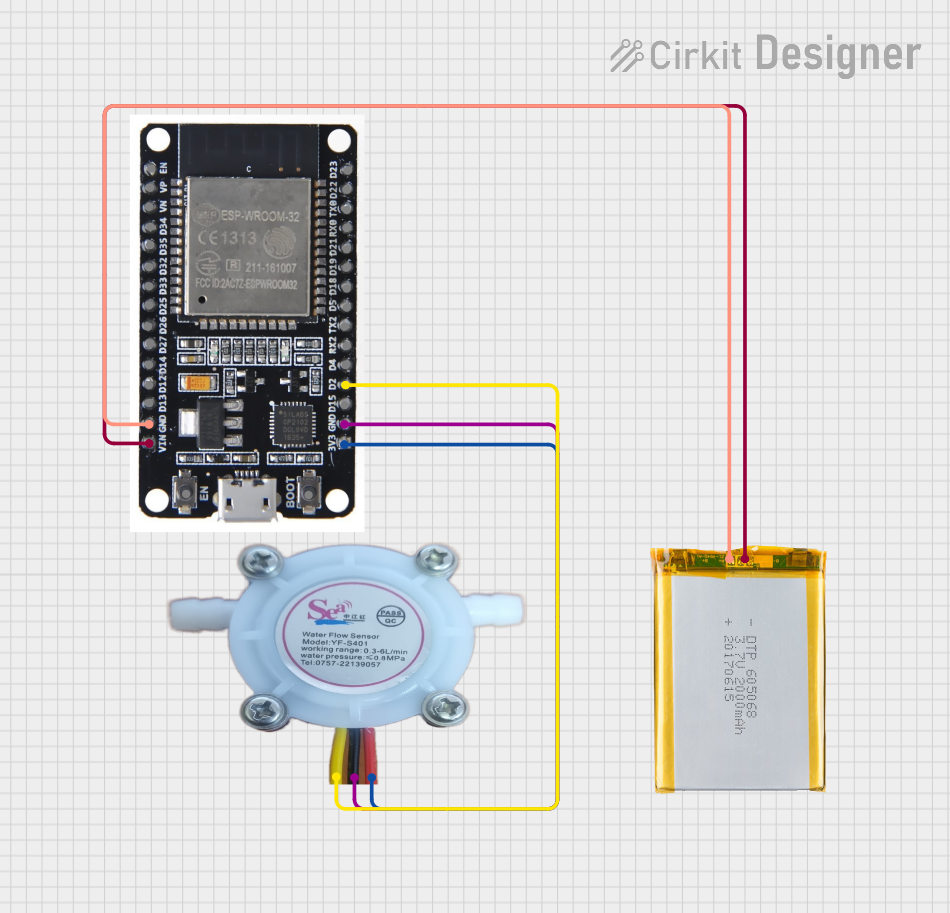
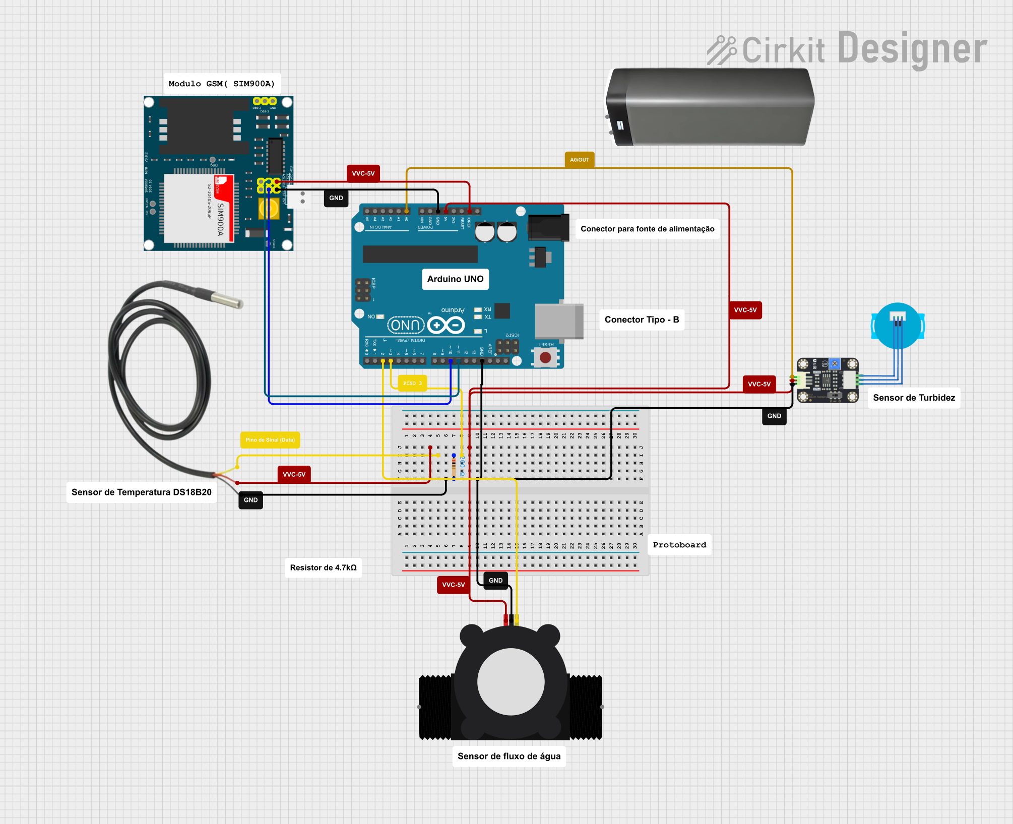
  1. Power Supply: Connect the VCC pin to a 5-18V DC power supply and the GND pin to the ground of your system.
  2. Signal Reading: Connect the Signal Output pin to a digital input pin on your microcontroller (e.g., Arduino UNO).
  3. Mounting: Ensure the sensor is securely mounted in line with the water flow direction indicated by the arrow on the sensor body.

Best Practices

  • Use a pull-up resistor (typically 10kΩ) between the signal output and VCC if your microcontroller does not have an internal pull-up on the digital input pin.
  • Ensure that the water temperature is within the specified operating range to avoid damage to the sensor.
  • Avoid introducing air bubbles into the system as they can cause inaccurate readings.
  • Regularly check for any debris or obstruction in the water path that may affect the sensor's performance.

Example Arduino Code

// Define the connection pin and the pulse count
const int sensorPin = 2; // Digital pin connected to the sensor's output
volatile int pulseCount; // Volatile because it is in an interrupt context

// Interrupt Service Routine for the flow sensor
void flowRatePulse() {
  pulseCount++;
}

void setup() {
  Serial.begin(9600);
  pinMode(sensorPin, INPUT);
  attachInterrupt(digitalPinToInterrupt(sensorPin), flowRatePulse, RISING); // Attach the interrupt
}

void loop() {
  pulseCount = 0; // Reset the pulse counter
  interrupts(); // Enable interrupts
  delay(1000); // Wait 1 second
  noInterrupts(); // Disable interrupts

  // Calculate the flow rate in L/min
  // Sensor frequency (Hz) = 7.5 * Q (L/min)
  // Pulse frequency (Hz) = 7.5 * flow rate in L/min
  // Note: The flow rate unit from this calculation is in L/min
  float flowRate = pulseCount / 7.5;
  Serial.print("Flow rate: ");
  Serial.print(flowRate);
  Serial.println(" L/min");
}

Troubleshooting and FAQs

Common Issues

  • No Signal Output: Ensure the sensor is properly powered and the signal wire is connected to the correct digital pin on the microcontroller.
  • Inaccurate Readings: Check for air bubbles or debris in the water flow. Verify that the water temperature is within the operating range.
  • Erratic Readings: Ensure there is no electrical noise affecting the signal. Use a pull-up resistor if necessary.

FAQs

Q: Can the sensor be used with hot water? A: The sensor can operate within a temperature range of -25 to +80°C. Ensure the water temperature does not exceed this range.

Q: How can I calibrate the sensor for accurate readings? A: Calibration involves comparing the sensor output with a known flow rate. Adjust the calculation in the code accordingly to match the known flow rate.

Q: Is the sensor waterproof? A: The sensor is designed to measure water flow within its body but is not rated for submersion or exposure to moisture outside its intended flow path.

Q: What is the lifespan of the sensor? A: The lifespan depends on usage conditions but is generally expected to be long when used within the specified parameters.

For further assistance, please contact the manufacturer or refer to the official datasheet for the YF-S401 Water Flow Rate Sensor.