How to Use Adafruit 16x8 LED Matrix Backpack Blue: Examples, Pinouts, and Specs
Introduction
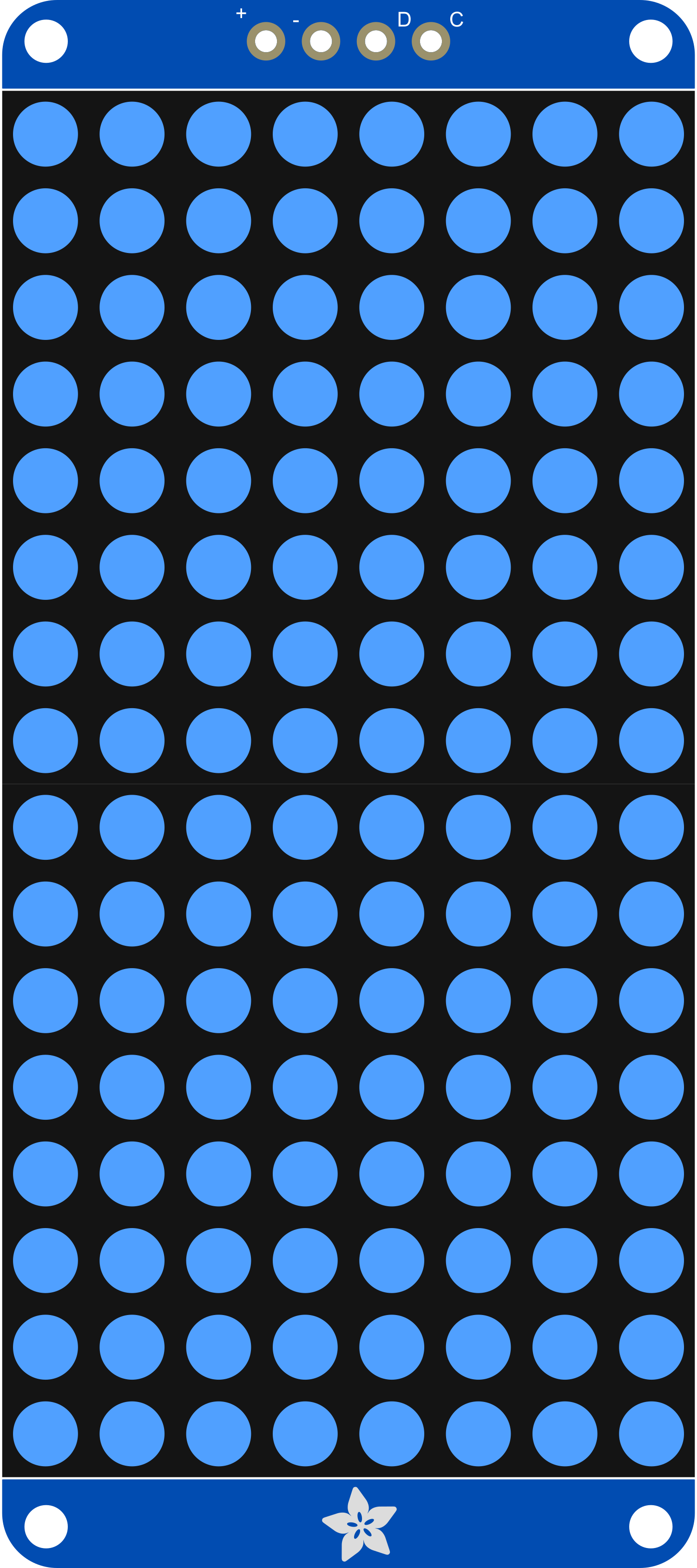
The Adafruit 16x8 LED Matrix Backpack Blue is a compact and versatile display module that allows users to add a bright, eye-catching display to their projects. This LED matrix has 16 columns and 8 rows of blue LEDs, controlled by the HT16K33 driver chip that communicates over I2C. It's perfect for displaying alphanumeric characters, simple icons, and animations. Common applications include wearable electronics, message boards, and custom clocks.
Explore Projects Built with Adafruit 16x8 LED Matrix Backpack Blue
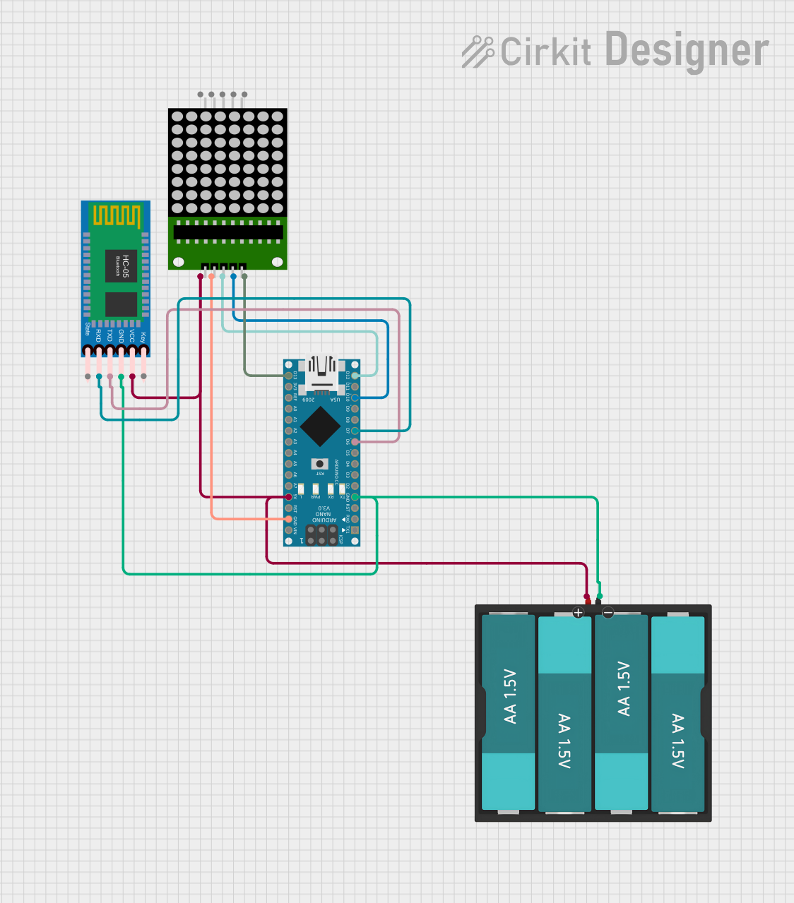

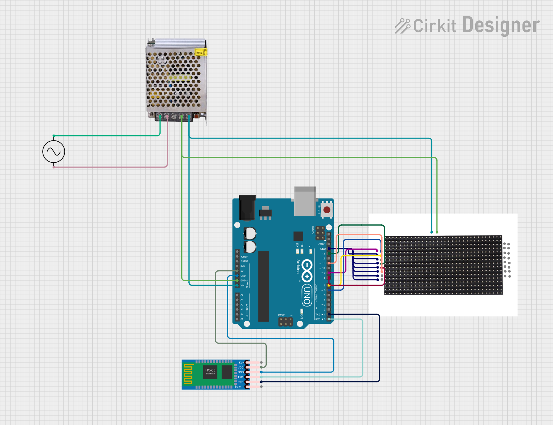
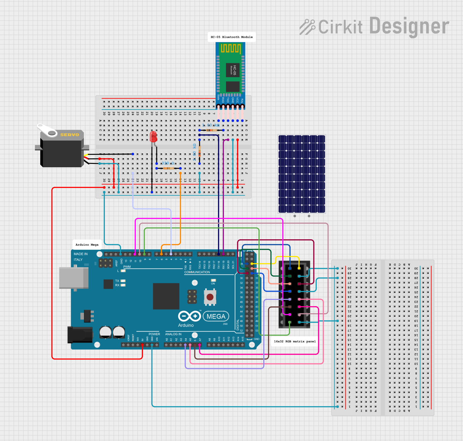
Explore Projects Built with Adafruit 16x8 LED Matrix Backpack Blue
Technical Specifications
Key Technical Details
- LED Color: Blue
- Matrix Size: 16 columns x 8 rows
- Communication: I2C interface
- Operating Voltage: 4.5V - 5.5V
- Max Current (with all LEDs on): 320mA
- Driver IC: HT16K33
Pin Configuration and Descriptions
| Pin | Description |
|---|---|
| GND | Ground connection |
| VCC | Power supply (4.5V - 5.5V) |
| SDA | I2C data line |
| SCL | I2C clock line |
| ADDR | Address selection pin (connect to GND or VCC to set I2C address) |
Usage Instructions
Integration with a Circuit
- Power Connections: Connect the VCC pin to a 5V supply and the GND pin to ground.
- I2C Connections: Connect the SDA and SCL pins to the corresponding SDA and SCL pins on your microcontroller (e.g., Arduino UNO).
- Address Selection: If using multiple displays, set unique I2C addresses by connecting the ADDR pin to GND or VCC.
Best Practices
- Use a current-limiting resistor if powering many LED matrices to prevent damage.
- Avoid running all LEDs at maximum brightness to reduce power consumption.
- Ensure that the I2C bus has pull-up resistors, typically 4.7kΩ to 10kΩ.
Example Code for Arduino UNO
#include <Wire.h>
#include "Adafruit_LEDBackpack.h"
#include "Adafruit_GFX.h"

Adafruit_8x16matrix matrix = Adafruit_8x16matrix();

void setup() {
  matrix.begin(0x70); // Initialize the display with its I2C address
  matrix.setBrightness(10); // Set brightness level (0 is dim, 15 is bright)
}

void loop() {
  matrix.clear(); // Clear the display buffer
  matrix.setCursor(0, 0); // Set cursor at top-left corner
  matrix.print("Hello"); // Print a message
  matrix.writeDisplay(); // Update the display with the buffer content
  delay(2000); // Wait for 2 seconds
}
Troubleshooting and FAQs
Common Issues
- Display Not Lighting Up: Ensure that the power supply is connected correctly and the I2C address is set properly.
- Dim or Flickering LEDs: Check the power supply for adequate current and stable voltage.
- Garbled Display: Make sure the I2C connections are secure and there are no loose wires.
Solutions and Tips
- If using multiple LED matrices, verify that each has a unique I2C address.
- Use the
setBrightness()function to adjust the display brightness to a suitable level. - Always call
writeDisplay()after making changes to the display buffer to update the actual display.
FAQs
Q: Can I use this LED matrix with a 3.3V microcontroller? A: Yes, but ensure that the logic levels are compatible, and you may need level shifters for stable operation.
Q: How do I display custom characters or animations?
A: You can create custom bitmaps and use the drawBitmap() function to display them. For animations, update the display buffer in a loop with a delay.
Q: How many of these LED matrices can I chain together? A: You can chain up to 8 matrices with unique I2C addresses on the same I2C bus.
For further assistance, consult the Adafruit support forums or the product's official documentation.