Cirkit Designer Logo
Cirkit Designer
Your all-in-one circuit design IDE
Home / 
Component Documentation

How to Use 50W DC-DC Converter: Examples, Pinouts, and Specs

Image of 50W DC-DC Converter
Cirkit Designer LogoDesign with 50W DC-DC Converter in Cirkit Designer

Introduction

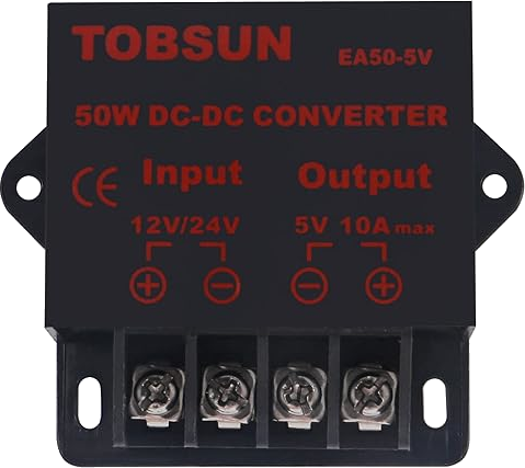
The TOBSUN EA50-5V is a 50W DC-DC Converter designed to efficiently convert one DC voltage level to another. With a high efficiency of over 85%, this converter is ideal for a wide range of applications, including but not limited to power supplies for computers, telecommunications equipment, and industrial machinery. Its robust design and high power output make it suitable for demanding environments where reliable voltage conversion is critical.

Explore Projects Built with 50W DC-DC Converter

Use Cirkit Designer to design, explore, and prototype these projects online. Some projects support real-time simulation. Click "Open Project" to start designing instantly!
Battery-Powered DC-DC Converter System for Multi-Voltage Power Distribution
Image of test 1 ih: A project utilizing 50W DC-DC Converter in a practical application
This circuit converts a 38.5V battery output to multiple lower voltage levels using a series of DC-DC converters and a power module. It includes an emergency stop switch for safety and distributes power to various components such as a relay module, USB ports, and a bus servo adaptor.
Cirkit Designer LogoOpen Project in Cirkit Designer
DC-DC Converter and Relay Module Power Distribution System
Image of relay: A project utilizing 50W DC-DC Converter in a practical application
This circuit consists of a DC-DC converter powering a 6-channel power module, which in turn supplies 5V to a 2-relay module. The power module distributes the converted voltage to the relay module, enabling it to control external devices.
Cirkit Designer LogoOpen Project in Cirkit Designer
Multi-Stage Voltage Regulation and Indicator LED Circuit
Image of Subramanyak_Power_Circuit: A project utilizing 50W DC-DC Converter in a practical application
This circuit is designed for power management, featuring buck and boost converters for voltage adjustment, and linear regulators for stable voltage output. It includes LEDs for status indication, and terminal blocks for external connections.
Cirkit Designer LogoOpen Project in Cirkit Designer
Battery-Powered USB Charger with LED Indicator and DC Motor
Image of Copy of Hand Crank mobile charger : A project utilizing 50W DC-DC Converter in a practical application
This circuit converts AC power to DC using a bridge rectifier and regulates the voltage to 5V with a 7805 voltage regulator. It powers a USB port and indicates power status with an LED, while also providing a charging interface through a multi-charging cable.
Cirkit Designer LogoOpen Project in Cirkit Designer

Explore Projects Built with 50W DC-DC Converter

Use Cirkit Designer to design, explore, and prototype these projects online. Some projects support real-time simulation. Click "Open Project" to start designing instantly!
Image of test 1 ih: A project utilizing 50W DC-DC Converter in a practical application
Battery-Powered DC-DC Converter System for Multi-Voltage Power Distribution
This circuit converts a 38.5V battery output to multiple lower voltage levels using a series of DC-DC converters and a power module. It includes an emergency stop switch for safety and distributes power to various components such as a relay module, USB ports, and a bus servo adaptor.
Cirkit Designer LogoOpen Project in Cirkit Designer
Image of relay: A project utilizing 50W DC-DC Converter in a practical application
DC-DC Converter and Relay Module Power Distribution System
This circuit consists of a DC-DC converter powering a 6-channel power module, which in turn supplies 5V to a 2-relay module. The power module distributes the converted voltage to the relay module, enabling it to control external devices.
Cirkit Designer LogoOpen Project in Cirkit Designer
Image of Subramanyak_Power_Circuit: A project utilizing 50W DC-DC Converter in a practical application
Multi-Stage Voltage Regulation and Indicator LED Circuit
This circuit is designed for power management, featuring buck and boost converters for voltage adjustment, and linear regulators for stable voltage output. It includes LEDs for status indication, and terminal blocks for external connections.
Cirkit Designer LogoOpen Project in Cirkit Designer
Image of Copy of Hand Crank mobile charger : A project utilizing 50W DC-DC Converter in a practical application
Battery-Powered USB Charger with LED Indicator and DC Motor
This circuit converts AC power to DC using a bridge rectifier and regulates the voltage to 5V with a 7805 voltage regulator. It powers a USB port and indicates power status with an LED, while also providing a charging interface through a multi-charging cable.
Cirkit Designer LogoOpen Project in Cirkit Designer

Technical Specifications

Key Technical Details

  • Input Voltage Range: 36V to 72V DC
  • Output Voltage: 5V DC
  • Output Power: 50W maximum
  • Efficiency: >85%
  • Isolation Voltage: 1500V DC
  • Operating Temperature Range: -40°C to +85°C
  • Switching Frequency: 300kHz

Pin Configuration and Descriptions

Pin Number Description Notes
1 Vout (+) Positive output voltage
2 Vout (-) Negative output voltage (GND)
3 Vin (+) Positive input voltage
4 Vin (-) Negative input voltage (GND)
5 Trim Output voltage trim (optional)
6 Remote On/Off Control pin to enable/disable
7 Sense (+) Output voltage sense (optional)
8 Sense (-) Output voltage sense (optional)

Usage Instructions

How to Use the Component in a Circuit

  1. Input Connection: Connect the input voltage source to pins 3 (Vin +) and 4 (Vin -). Ensure that the source voltage is within the specified input voltage range of the converter.

  2. Output Connection: Connect the load to pins 1 (Vout +) and 2 (Vout -). The output voltage is factory set to 5V DC.

  3. Trimming Output Voltage (Optional): If necessary, the output voltage can be adjusted by applying a variable resistance or voltage to pin 5 (Trim).

  4. Remote On/Off (Optional): The converter can be turned on or off remotely by applying a logic signal to pin 6.

  5. Voltage Sensing (Optional): For applications requiring precise voltage regulation, connect pins 7 (Sense +) and 8 (Sense -) to the load.

Important Considerations and Best Practices

  • Ensure that the input voltage does not exceed the maximum rating to prevent damage to the converter.
  • Do not exceed the maximum output power rating of 50W.
  • Provide adequate cooling to maintain the converter within the operating temperature range.
  • Use proper filtering on both the input and output to minimize noise and voltage spikes.
  • If the remote on/off feature is not used, ensure that pin 6 is left open or connected to Vin (-) to keep the converter in the 'on' state.

Troubleshooting and FAQs

Common Issues and Solutions

  • Converter does not power on: Check input voltage and connections to pins 3 and 4. Ensure that pin 6 is not inadvertently pulling the converter into the 'off' state.
  • Output voltage is incorrect: Verify the load does not exceed 50W. If using the trim function, adjust the trim setting. Check connections to sense pins if used.
  • Converter overheats: Ensure adequate airflow and cooling. Reduce the load if it exceeds the specified maximum power rating.

FAQs

Q: Can the output voltage be adjusted? A: Yes, the output voltage can be adjusted by using the trim pin (pin 5).

Q: What is the purpose of the sense pins? A: The sense pins (pins 7 and 8) provide feedback to the converter for more accurate voltage regulation at the load.

Q: Is the converter isolated? A: Yes, the converter has an isolation voltage of 1500V DC between input and output.

Q: Can this converter be used with an Arduino UNO? A: While the output voltage is compatible with an Arduino UNO, this converter is typically used for higher power applications. For Arduino projects, a lower power DC-DC converter is usually sufficient.

Note: This documentation is for informational purposes only. Always consult the manufacturer's datasheet for the most accurate and detailed information about the component.