How to Use M12 12 pin: Examples, Pinouts, and Specs
Introduction
The M12 12 Pin connector, manufactured by ANY, is a circular connector designed for industrial applications. It features 12 pins and is widely used for connecting sensors, actuators, and other devices in harsh environments. Its robust design ensures reliable performance in challenging conditions, such as high vibration, moisture, and dust.
Explore Projects Built with M12 12 pin


Explore Projects Built with M12 12 pin
Common Applications and Use Cases
- Industrial automation systems
- Robotics and motion control
- Factory equipment and machinery
- Process control and instrumentation
- Outdoor and harsh environment applications
Technical Specifications
Key Technical Details
| Parameter | Specification |
|---|---|
| Manufacturer | ANY |
| Part ID | M12 12 Pin |
| Number of Pins | 12 |
| Connector Type | Circular |
| Contact Material | Gold-plated brass |
| Insulation Resistance | ≥ 100 MΩ |
| Rated Voltage | 250V AC/DC |
| Rated Current | 4A per pin |
| Operating Temperature | -40°C to +85°C |
| IP Rating | IP67 (dust-tight and waterproof) |
| Mating Cycles | ≥ 500 |
Pin Configuration and Descriptions
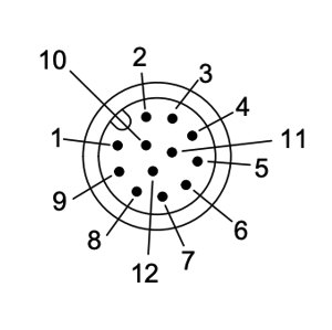
The M12 12 Pin connector features 12 pins arranged in a circular pattern. Below is the pinout configuration:
| Pin Number | Description | Typical Use Case |
|---|---|---|
| 1 | Power Supply (+) | Positive voltage input |
| 2 | Power Supply (-) | Ground connection |
| 3 | Signal 1 | Sensor/actuator signal |
| 4 | Signal 2 | Sensor/actuator signal |
| 5 | Signal 3 | Sensor/actuator signal |
| 6 | Signal 4 | Sensor/actuator signal |
| 7 | Signal 5 | Sensor/actuator signal |
| 8 | Signal 6 | Sensor/actuator signal |
| 9 | Reserved | Custom application |
| 10 | Reserved | Custom application |
| 11 | Shield | Cable shielding/grounding |
| 12 | Shield | Cable shielding/grounding |
Usage Instructions
How to Use the M12 12 Pin Connector in a Circuit
Wiring the Connector:
- Identify the pin numbers on the connector using the manufacturer’s datasheet or markings.
- Solder or crimp the wires to the corresponding pins based on your application’s requirements.
- Ensure proper insulation and strain relief to avoid damage to the wires.
Connecting to Devices:
- Align the connector with the mating socket and gently push it in.
- Rotate the locking nut clockwise to secure the connection. Do not overtighten.
Power and Signal Connections:
- Use pins 1 and 2 for power supply connections.
- Use pins 3 to 8 for transmitting signals between devices.
- Pins 11 and 12 can be used for shielding to reduce electromagnetic interference (EMI).
Testing the Connection:
- Verify continuity using a multimeter to ensure all pins are correctly connected.
- Power on the system and test the functionality of connected devices.
Important Considerations and Best Practices
- Environmental Protection: Ensure the connector is properly sealed to maintain its IP67 rating.
- Cable Selection: Use shielded cables for applications in high-EMI environments.
- Mating Cycles: Avoid excessive mating and unmating to prolong the connector’s lifespan.
- Polarity: Double-check the polarity of power connections to prevent damage to devices.
- Torque: Use the recommended torque for securing the connector to avoid damage.
Example: Connecting to an Arduino UNO
The M12 12 Pin connector can be used to interface sensors or actuators with an Arduino UNO. Below is an example of connecting a sensor using the M12 connector:
Circuit Diagram
- Pin 1: Connect to Arduino 5V
- Pin 2: Connect to Arduino GND
- Pin 3: Connect to Arduino digital pin 2 (sensor signal)
Arduino Code
// Example code for reading a sensor connected via M12 12 Pin connector
const int sensorPin = 2; // Sensor signal connected to digital pin 2
int sensorValue = 0;     // Variable to store sensor reading

void setup() {
  pinMode(sensorPin, INPUT); // Set sensor pin as input
  Serial.begin(9600);        // Initialize serial communication
}

void loop() {
  sensorValue = digitalRead(sensorPin); // Read sensor value
  Serial.print("Sensor Value: ");       // Print sensor value to serial monitor
  Serial.println(sensorValue);
  delay(500);                           // Wait for 500ms before next reading
}
Troubleshooting and FAQs
Common Issues and Solutions
| Issue | Possible Cause | Solution |
|---|---|---|
| No power to connected device | Incorrect wiring or loose connection | Verify wiring and ensure secure mating |
| Signal interference or noise | Poor shielding or EMI | Use shielded cables and connect pins 11/12 |
| Connector not mating properly | Misalignment or debris in connector | Clean connector and align properly |
| Device not responding | Incorrect pin mapping | Double-check pin configuration |
FAQs
Can the M12 12 Pin connector be used outdoors?
- Yes, the connector is rated IP67, making it suitable for outdoor use in harsh environments.
What is the maximum current rating per pin?
- Each pin can handle up to 4A of current.
How many mating cycles can the connector withstand?
- The connector is rated for at least 500 mating cycles.
Can I use this connector for high-frequency signals?
- Yes, but ensure proper shielding (pins 11 and 12) to minimize signal degradation.
By following this documentation, users can effectively integrate the M12 12 Pin connector into their projects and troubleshoot common issues with ease.