How to Use LM3914/5/6: Examples, Pinouts, and Specs

 Design with LM3914/5/6 in Cirkit Designer
Introduction
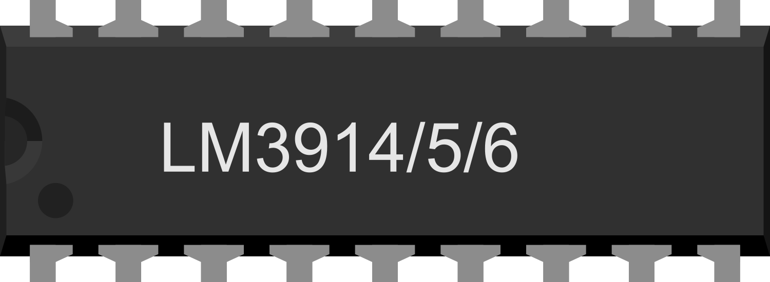
The LM3914/5/6 series are integrated circuits designed for driving arrays of LEDs based on an analog input voltage. These chips can drive up to 10 LEDs, providing a visual analog level indicator that is easy to read and interpret. They are widely used in applications such as battery monitors, audio level indicators, and various types of signal strength displays.
Explore Projects Built with LM3914/5/6

 Open Project in Cirkit Designer
 Open Project in Cirkit Designer
 Open Project in Cirkit Designer
 Open Project in Cirkit Designer
Explore Projects Built with LM3914/5/6

 Open Project in Cirkit Designer
 Open Project in Cirkit Designer
 Open Project in Cirkit Designer
 Open Project in Cirkit Designer
Common Applications
- Audio equipment (VU meters)
- Battery level indicators
- Signal strength meters
- Power meters
Technical Specifications
Key Technical Details
- Operating Voltage: Typically 3V to 18V (LM3914), 3V to 25V (LM3915), 3V to 35V (LM3916)
- Output Current: Adjustable from 2 mA to 30 mA per LED
- Display Modes: Bar or dot display mode selectable
- LED Current Regulation: No external resistors required
- Package: DIP (Dual In-line Package) or SOIC (Small Outline Integrated Circuit)
Pin Configuration and Descriptions
| Pin Number | LM3914/5/6 Pin Name | Description |
|---|---|---|
| 1 | V+ | Positive supply voltage input |
| 2 | LED1 | Output to drive LED 1 |
| 3 | LED2 | Output to drive LED 2 |
| 4 | LED3 | Output to drive LED 3 |
| 5 | LED4 | Output to drive LED 4 |
| 6 | LED5 | Output to drive LED 5 |
| 7 | LED6 | Output to drive LED 6 |
| 8 | LED7 | Output to drive LED 7 |
| 9 | LED8 | Output to drive LED 8 |
| 10 | LED9 | Output to drive LED 9 |
| 11 | LED10 | Output to drive LED 10 |
| 12 | Mode | Bar/Dot display mode select (ground for bar, open for dot) |
| 13 | REF OUT | Reference voltage output |
| 14 | REF ADJ | Reference adjust, allows setting LED current |
| 15 | RLO | Low side of resistor divider |
| 16 | Signal | Analog signal input |
| 17 | RHI | High side of resistor divider |
| 18 | V- | Ground |
Usage Instructions
How to Use the Component in a Circuit
- Connect the V+ pin to a positive voltage within the specified range.
- Connect the V- pin to the ground.
- Set the desired LED current by connecting a resistor between the REF OUT and REF ADJ pins.
- Connect the analog signal to the Signal pin.
- Connect LEDs to the respective LED output pins with the anode to the IC and cathode to ground.
- Optionally, set the display mode by connecting the Mode pin to ground for bar mode or leaving it open for dot mode.
Important Considerations and Best Practices
- Ensure that the power supply voltage does not exceed the maximum rating for the specific model.
- Use current-limiting resistors if the supply voltage significantly exceeds the LED forward voltage to prevent damage.
- Avoid running the IC at the maximum current rating for extended periods to prevent overheating.
- Use a bypass capacitor (typically 0.1 µF) between the V+ and V- pins to filter out noise.
Example Circuit and Arduino Code
// Example code for driving an LM3914/5/6 with an Arduino UNO

const int analogPin = A0; // Analog input pin that the potentiometer is attached to
const int ledCount = 10;  // Number of LEDs in the bar graph

int ledPins[] = {2, 3, 4, 5, 6, 7, 8, 9, 10, 11}; // Array of pin numbers to which LEDs are connected

void setup() {
  // Loop over the pin array and set them all to output:
  for (int thisLed = 0; thisLed < ledCount; thisLed++) {
    pinMode(ledPins[thisLed], OUTPUT);
  }
}

void loop() {
  // Read the potentiometer:
  int sensorReading = analogRead(analogPin);
  // Map the result to a range from 0 to the number of LEDs:
  int ledLevel = map(sensorReading, 0, 1023, 0, ledCount);

  // Loop over the LED pins:
  for (int thisLed = 0; thisLed < ledCount; thisLed++) {
    // If the array element's index is less than ledLevel,
    // turn the pin for this element on:
    if (thisLed < ledLevel) {
      digitalWrite(ledPins[thisLed], HIGH);
    }
    // Turn off all pins higher than the ledLevel:
    else {
      digitalWrite(ledPins[thisLed], LOW);
    }
  }
}
Troubleshooting and FAQs
Common Issues
- LEDs not lighting up: Check the power supply and connections. Ensure the input signal is within the expected range.
- Only one LED lights up in dot mode: This is expected behavior in dot mode. To display a bar, connect the Mode pin to ground.
- LEDs are too dim or too bright: Adjust the current setting resistor between REF OUT and REF ADJ pins.
Solutions and Tips for Troubleshooting
- Double-check wiring against the pin configuration table.
- Verify that the power supply is stable and within the specified voltage range.
- Use a multimeter to check the voltage at the Signal pin and ensure it varies as expected.
- Ensure that the REF OUT and REF ADJ pins are correctly set up to regulate the LED current.
FAQs
Q: Can I drive more than 10 LEDs with a single LM3914/5/6? A: No, the LM3914/5/6 is designed to drive up to 10 LEDs. To drive more, you can cascade multiple ICs.
Q: What is the difference between the LM3914, LM3915, and LM3916? A: The main difference is the internal voltage reference scaling. The LM3914 has a linear scale, the LM3915 has a logarithmic (dB) scale, and the LM3916 has a VU meter scale.
Q: Can I use the LM3914/5/6 with a microcontroller like an Arduino? A: Yes, you can use these ICs with an Arduino or other microcontrollers to provide visual feedback for an analog signal.