How to Use Gear Motor with integrated Encoder: Examples, Pinouts, and Specs

Introduction
The Gear Motor with Integrated Encoder by Naroote is a versatile and efficient component that combines a motor, a gearbox, and an encoder into a single unit. This design allows for precise control of speed, torque, and position, making it ideal for applications requiring high accuracy and feedback. The integrated encoder provides real-time feedback on the motor's rotation, enabling closed-loop control systems for enhanced performance.
Explore Projects Built with Gear Motor with integrated Encoder

Explore Projects Built with Gear Motor with integrated Encoder
Common Applications and Use Cases
- Robotics: For precise movement and positioning of robotic arms or wheels.
- CNC Machines: Ensures accurate control of cutting tools or workpieces.
- Automated Systems: Used in conveyor belts, actuators, and other industrial automation.
- DIY Projects: Ideal for hobbyists building motorized systems with feedback control.
- Electric Vehicles: For controlling wheel speed and torque.
Technical Specifications
Key Technical Details
| Parameter | Specification |
|---|---|
| Operating Voltage | 6V to 12V |
| Rated Current | 0.5A to 1.2A (depending on load) |
| Gear Ratio | 1:30 |
| Encoder Resolution | 11 pulses per revolution (PPR) |
| Maximum Torque | 2.5 kg·cm |
| No-Load Speed | 200 RPM (at 12V) |
| Shaft Diameter | 6 mm |
| Operating Temperature | -10°C to 50°C |
| Dimensions | 70 mm x 30 mm x 25 mm |
| Weight | 120 g |
Pin Configuration and Descriptions
The gear motor with an integrated encoder typically has 6 wires for connection. Below is the pin configuration:
| Pin/Wire Color | Function | Description |
|---|---|---|
| Red | Motor Power (+) | Connect to the positive terminal of the power supply. |
| Black | Motor Power (-) | Connect to the negative terminal of the power supply. |
| Green | Encoder A Output | Outputs the first channel of encoder pulses. |
| Yellow | Encoder B Output | Outputs the second channel of encoder pulses. |
| Blue | Encoder Power (+) | Connect to the positive terminal of the encoder power supply (5V). |
| White | Encoder Power (-) | Connect to the ground of the encoder power supply. |
Usage Instructions
How to Use the Component in a Circuit
Powering the Motor:
- Connect the red wire to the positive terminal of your power supply (6V to 12V).
- Connect the black wire to the negative terminal of your power supply.
- Ensure the power supply can handle the motor's current requirements.
Connecting the Encoder:
- Connect the blue wire to a 5V power source for the encoder.
- Connect the white wire to the ground of the encoder power source.
- Connect the green and yellow wires to the microcontroller's digital input pins to read the encoder signals.
Reading Encoder Signals:
- The encoder outputs two square wave signals (A and B) that are 90° out of phase. These signals can be used to determine the direction and speed of the motor.
Controlling the Motor:
- Use an H-bridge motor driver to control the motor's speed and direction.
- Pulse Width Modulation (PWM) can be applied to the motor power pins for speed control.
Important Considerations and Best Practices
- Power Supply: Ensure the power supply voltage matches the motor's operating range (6V to 12V). Using a voltage outside this range may damage the motor.
- Current Handling: Use a power supply and motor driver capable of handling the motor's peak current.
- Encoder Signal Noise: Use pull-up resistors or software debouncing to filter noise from the encoder signals.
- Mounting: Secure the motor properly to avoid vibrations that could affect performance.
- Heat Management: Avoid prolonged operation at high loads to prevent overheating.
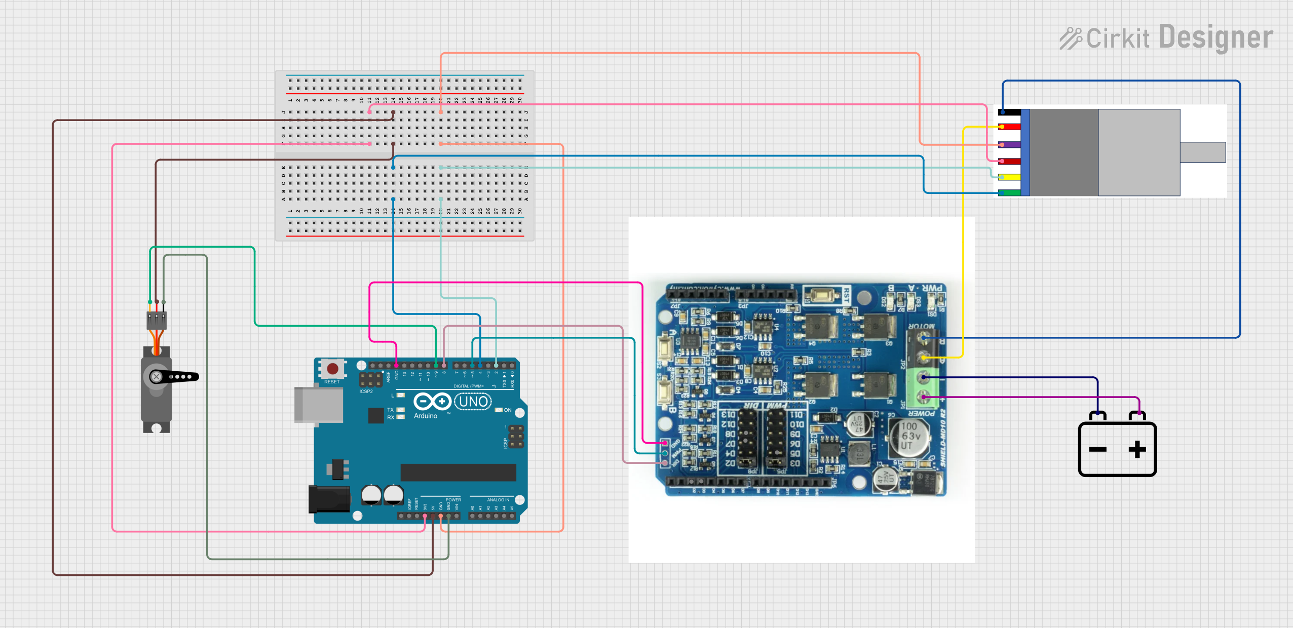
Example: Connecting to an Arduino UNO
Below is an example of how to connect and use the gear motor with an integrated encoder with an Arduino UNO:
Circuit Connections
- Motor Power: Connect the red and black wires to an H-bridge motor driver (e.g., L298N).
- Encoder:
- Connect the blue wire to the Arduino's 5V pin.
- Connect the white wire to the Arduino's GND pin.
- Connect the green wire to digital pin 2.
- Connect the yellow wire to digital pin 3.
Arduino Code
// Define encoder pins
const int encoderPinA = 2; // Green wire
const int encoderPinB = 3; // Yellow wire

volatile int encoderCount = 0; // Variable to store encoder count

void setup() {
  pinMode(encoderPinA, INPUT); // Set encoder pin A as input
  pinMode(encoderPinB, INPUT); // Set encoder pin B as input

  // Attach interrupt to encoder pin A
  attachInterrupt(digitalPinToInterrupt(encoderPinA), encoderISR, CHANGE);

  Serial.begin(9600); // Initialize serial communication
}

void loop() {
  // Print the encoder count to the Serial Monitor
  Serial.print("Encoder Count: ");
  Serial.println(encoderCount);
  delay(500); // Delay for readability
}

// Interrupt Service Routine (ISR) for encoder
void encoderISR() {
  // Read the state of encoder pin B
  int stateB = digitalRead(encoderPinB);

  // Determine direction based on state of pin B
  if (stateB == HIGH) {
    encoderCount++; // Clockwise rotation
  } else {
    encoderCount--; // Counterclockwise rotation
  }
}
Troubleshooting and FAQs
Common Issues and Solutions
Motor Not Spinning:
- Cause: Insufficient power supply or incorrect wiring.
- Solution: Verify the power supply voltage and current. Check the red and black wire connections.
Encoder Signals Not Detected:
- Cause: Incorrect wiring or insufficient pull-up resistors.
- Solution: Ensure the encoder wires are connected correctly. Add pull-up resistors if necessary.
Inconsistent Encoder Readings:
- Cause: Electrical noise or loose connections.
- Solution: Use shielded cables for encoder wires and secure all connections.
Motor Overheating:
- Cause: Prolonged operation at high loads.
- Solution: Reduce the load or provide adequate cooling.
FAQs
Q: Can I use a 3.3V microcontroller with this encoder?
A: Yes, but ensure the encoder's output signals are compatible with the microcontroller's input voltage levels.Q: What is the purpose of the encoder?
A: The encoder provides feedback on the motor's rotation, enabling precise control of speed and position.Q: Can I reverse the motor's direction?
A: Yes, by reversing the polarity of the motor power wires or using an H-bridge motor driver.Q: How do I calculate the motor's speed using the encoder?
A: Count the encoder pulses over a fixed time interval and multiply by the encoder resolution.
This concludes the documentation for the Gear Motor with Integrated Encoder by Naroote.