How to Use 25V Voltage Divider Sensor Module: Examples, Pinouts, and Specs
Introduction
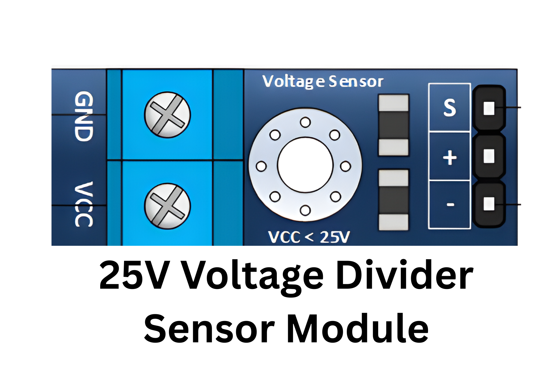
The 25V Voltage Divider Sensor Module is a compact and efficient device designed to safely measure high input voltages (up to 25V) by reducing them to a lower voltage level suitable for microcontroller or sensor inputs. This module is commonly used in applications where voltage monitoring is critical, such as battery management systems, power supply monitoring, and other electronic projects requiring safe voltage measurement.
By leveraging a simple resistor-based voltage divider circuit, this module ensures accurate voltage scaling while protecting sensitive components from high voltage levels.
Explore Projects Built with 25V Voltage Divider Sensor Module


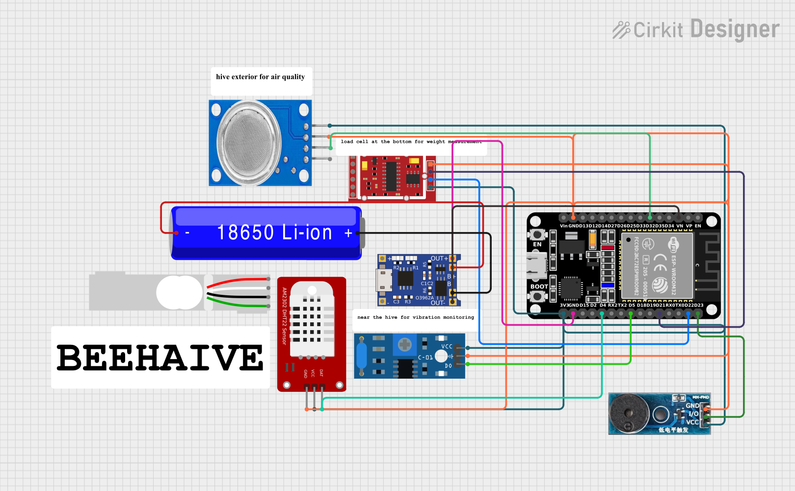
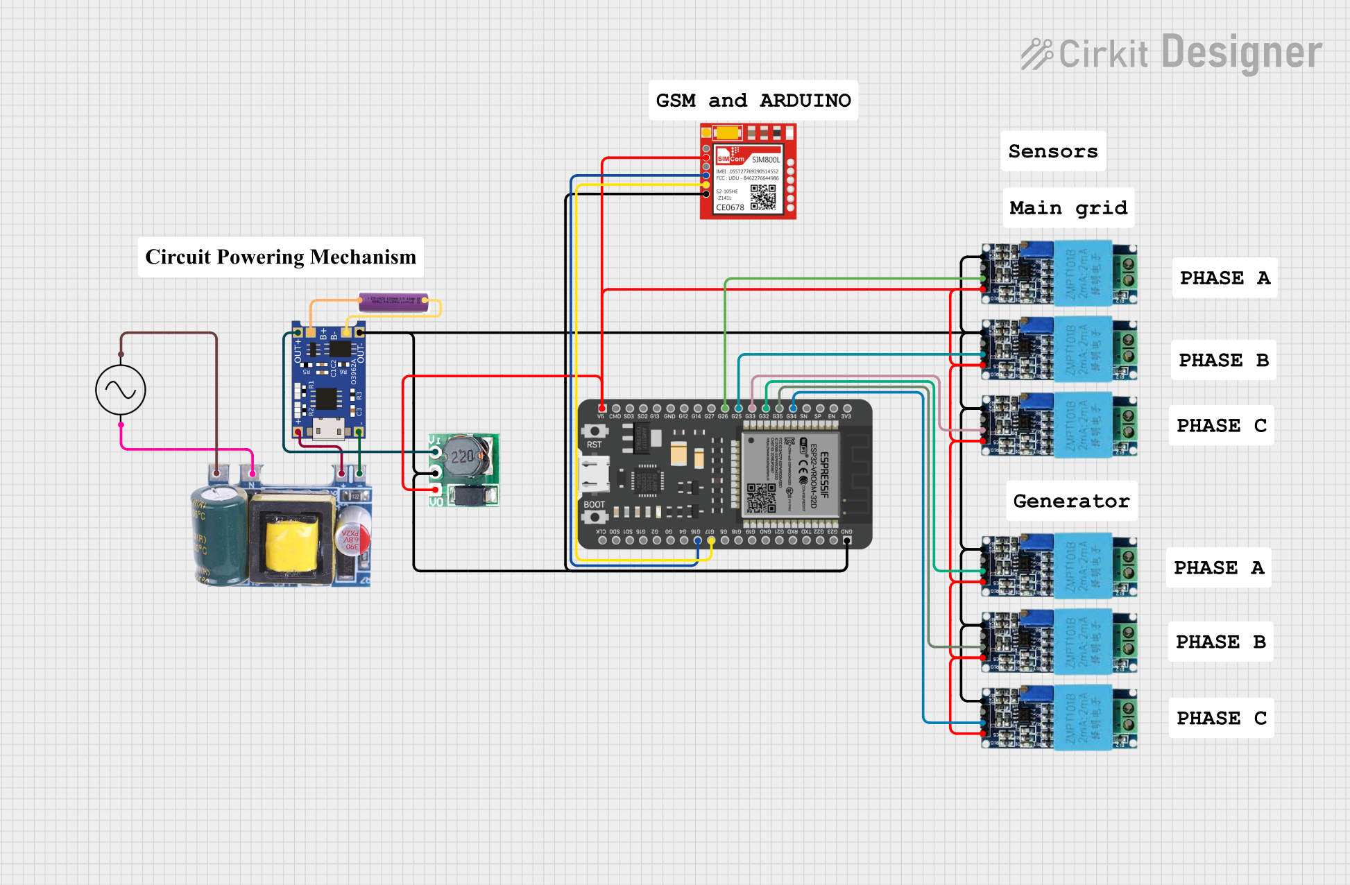
Explore Projects Built with 25V Voltage Divider Sensor Module
Common Applications
- Battery voltage monitoring in robotics and IoT devices
- Power supply voltage measurement
- Safe voltage scaling for microcontroller ADC (Analog-to-Digital Converter) inputs
- Educational and prototyping projects
Technical Specifications
Key Technical Details
| Parameter | Value |
|---|---|
| Input Voltage Range | 0V to 25V |
| Output Voltage Range | 0V to 5V |
| Voltage Divider Ratio | 5:1 |
| Accuracy | ±1% (depends on resistor tolerances) |
| Operating Temperature | -40°C to 85°C |
| Dimensions | ~25mm x 15mm x 10mm |
Pin Configuration and Descriptions
| Pin Name | Description |
|---|---|
VIN |
High voltage input (0V to 25V). Connect the voltage source to this pin. |
GND |
Ground connection. Connect to the ground of the circuit. |
VOUT |
Scaled-down voltage output (0V to 5V). Connect to the ADC pin of a microcontroller. |
Usage Instructions
How to Use the Component in a Circuit
Connect the Input Voltage:
- Attach the voltage source (up to 25V) to the
VINpin of the module. - Ensure the ground of the voltage source is connected to the
GNDpin of the module.
- Attach the voltage source (up to 25V) to the
Connect the Output Voltage:
- Connect the
VOUTpin to the ADC input of your microcontroller or any other voltage measurement device. - Ensure the microcontroller's ground is also connected to the module's
GNDpin.
- Connect the
Power the Microcontroller:
- Power your microcontroller as per its specifications. The module does not require a separate power supply.
Read the Scaled Voltage:
- The output voltage (
VOUT) is scaled down by a factor of 5. For example, if the input voltage is 25V, the output voltage will be 5V.
- The output voltage (
Important Considerations and Best Practices
- Input Voltage Limit: Do not exceed the maximum input voltage of 25V, as this may damage the module or connected devices.
- Resistor Tolerances: The accuracy of the voltage measurement depends on the precision of the resistors used in the module. For critical applications, verify the module's accuracy with a multimeter.
- ADC Resolution: Ensure your microcontroller's ADC resolution is sufficient to achieve the desired measurement accuracy.
- Noise Filtering: If the input voltage is noisy, consider adding a capacitor across the
VINandGNDpins to stabilize the signal.
Example: Using with Arduino UNO
Below is an example of how to use the 25V Voltage Divider Sensor Module with an Arduino UNO to measure a voltage source.
// Define the analog pin connected to the VOUT pin of the module
const int voltagePin = A0;

// Define the voltage divider ratio (5:1)
const float voltageDividerRatio = 5.0;

// Define the reference voltage of the Arduino (typically 5V)
const float referenceVoltage = 5.0;

void setup() {
  // Initialize serial communication for debugging
  Serial.begin(9600);
}

void loop() {
  // Read the analog value from the voltage divider module
  int analogValue = analogRead(voltagePin);

  // Convert the analog value to a voltage (0-5V range)
  float measuredVoltage = (analogValue / 1023.0) * referenceVoltage;

  // Scale the measured voltage back to the original input voltage
  float inputVoltage = measuredVoltage * voltageDividerRatio;

  // Print the input voltage to the Serial Monitor
  Serial.print("Input Voltage: ");
  Serial.print(inputVoltage);
  Serial.println(" V");

  // Wait for 1 second before the next reading
  delay(1000);
}
Troubleshooting and FAQs
Common Issues and Solutions
No Output Voltage on
VOUT:- Cause: The input voltage is not connected or is below the measurable range.
- Solution: Verify the connection to the
VINpin and ensure the input voltage is within the 0V to 25V range.
Inaccurate Voltage Readings:
- Cause: Resistor tolerances or ADC resolution may be affecting accuracy.
- Solution: Use a multimeter to verify the module's output voltage. If necessary, calibrate the measurement in your code by adjusting the
voltageDividerRatio.
Microcontroller Not Detecting Voltage:
- Cause: The
VOUTpin is not properly connected to the ADC pin. - Solution: Double-check the wiring and ensure the microcontroller's ground is connected to the module's ground.
- Cause: The
Module Overheating:
- Cause: Input voltage exceeds the 25V limit.
- Solution: Ensure the input voltage does not exceed the module's maximum rating.
FAQs
Q: Can this module measure negative voltages?
A: No, the module is designed to measure positive voltages only. Applying negative voltages may damage the module.
Q: Can I use this module with a 3.3V microcontroller?
A: Yes, but ensure the VOUT voltage does not exceed the ADC input range of your microcontroller. For a 3.3V system, the maximum input voltage should not exceed 16.5V (scaled down to 3.3V).
Q: How do I improve measurement accuracy?
A: Use a high-resolution ADC and ensure the resistors in the module have low tolerance values (e.g., 0.1%).
Q: Is the module suitable for AC voltage measurement?
A: No, this module is designed for DC voltage measurement only. For AC voltage, additional circuitry is required to rectify and scale the signal.
This documentation provides a comprehensive guide to using the 25V Voltage Divider Sensor Module effectively and safely.